AN1096 Datasheet Text
AN1096
Using the C30 piler to Interface SPI Serial EEPROMs with dsPIC33F and PIC24F
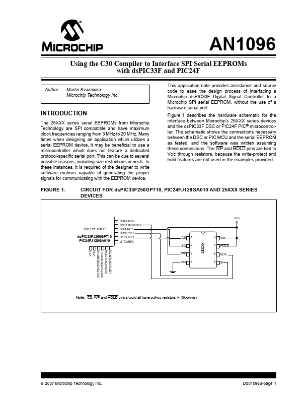
Author: Martin Kvasnicka Microchip Technology Inc. This application note provides assistance and source code to ease the design process of interfacing a Microchip dsPIC33F Digital Signal Controller to a Microchip SPI serial EEPROM, without the use of a hardware serial port. Figure 1 describes the hardware schematic for the interface between Microchip’s 25XXX series devices and the dsPIC33F DSC or PIC24F PIC® microcontroller. The schematic shows the connections necessary between the DSC or PIC MCU and the serial EEPROM as tested, and the software was written assuming these connections. The WP and HOLD pins are tied to VCC through resistors, because the write-protect and hold Features are not used in the examples provided.
INTRODUCTION
The 25XXX series serial EEPROMs from Microchip Technology are SPI patible and have maximum clock frequencies ranging from 3 MHz to 20 MHz. Many times when designing an application which utilizes a serial EEPROM device, it may be beneficial to use a microcontroller which does not feature a dedicated protocol-specific serial port. This can be due to several possible reasons, including size restrictions or costs. In these instances, it is required of the designer to write software routines capable of generating the proper signals for municating with the EEPROM device.
FIGURE 1:
CIRCUIT FOR dsPIC33F256GP710, PIC24FJ128GA010 AND 25XXX SERIES DEVICES
100 Pin TQFP dsPIC33FJ256GP710 PIC24FJ128GA010
VSS VDD U1CTS/CN20/RD14 U1RTS/CN21/RD15 U2RX/CN17/RF4 U2TX/CN18/RF5
SO WP Vss
2 3 4
25XXX
SDA1/RG3 SCK1/INT0/RF6 SDI1/RF7 SDO1/RF8 U1RX/RF2 U1TX/RF3
Vcc
CS
1
8 7 6 5
Vcc HOLD SCK SI
Note: CS, WP and HOLD pins should all have pull-up resistors...