J176
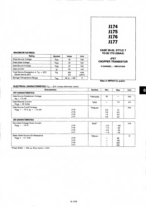
J174 J 175 J176 J177
MAXIMUM RATINGS
Rating Drain-Source Voltage Drain-Gate Voltage Gate-Source Voltage Gate Current
@Total Device Dissipation Ta = 25°C
Derate above 25°C Storage Temperature Range
Symbol v Ds Vdg VGS
'G
Tstg
Value 30 30 30 50 350
- 65 to + 1 50
Unit
Vdc
Vdc
Vdc m A m W m W/°C
°C
ELECTRICAL CHARACTERISTICS <TA = 25°C unless otherwise noted.)
OFF CHARACTERISTICS
Characteristic
Gate-Source Breakdown Voltage (JG = 1.0/i A)
Gate Reverse Current ... (Vqs = 20 Volts) Gate Source Cutoff Voltage
(Vds = -15V, Dl = -10n A)
ON CHARACTERISTICS
J174 J175 J176 J177
Zero-Gate-Voltage Drain Current
(VDS = -15 V)
J174 J175 J176 J177
Static Drain-Source On Resistance (VDS
- -0.1 Volt)
- Pulse Width = 300 ^s. Duty Cycle =s 3.0%.
J174 J175 J176 J177
CASE 29-02, STYLE 7
TO-92 (TO-226AA)
JFET
CHOPPER TRANSISTOR
- pchannel Depletion
Refer to MPF970 for graphs.
Symbol V (BR)GSS
!GSS v...