Datasheet4U Logo Datasheet4U.com

MC14469 - Addressable Asynchronous Receiver/Transmitter

Download the MC14469 datasheet PDF. This datasheet also covers the MC14469P variant, as both devices belong to the same addressable asynchronous receiver/transmitter family and are provided as variant models within a single manufacturer datasheet.

General Description

A0

These inputs are the address setting pins which contain the address match for the received signal.

A6 have on chip pull

up resistors.

C6 Command Word These pins are the readout of the general purpose command word

Key Features

  • n at the center of a receive clock period. The start bit is followed by eight data bits. Seven of the bits are compared against states of the address of the particular circuit (A0.
  • A6). Address is latched 31 clock cycles after the end of the start bit of the incoming address. The eighth bit signifies an address word “1” or a command word “0”. Next, a parity bit is received and checked by the internal logic for even parity. Finally a stop bit is received. At the completion of the cycle i.

📥 Download Datasheet

Note: The manufacturer provides a single datasheet file (MC14469P_MotorolaInc.pdf) that lists specifications for multiple related part numbers.

Full PDF Text Transcription (Reference)

The following content is an automatically extracted verbatim text from the original manufacturer datasheet and is provided for reference purposes only.

View original datasheet text
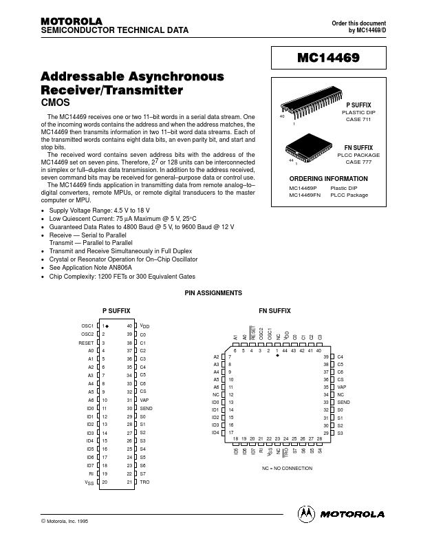
MOTOROLA SEMICONDUCTOR TECHNICAL DATA Order this document by MC14469/D MC14469 Addressable Asynchronous Receiver/Transmitter CMOS The MC14469 receives one or two 11–bit words in a serial data stream. One of the incoming words contains the address and when the address matches, the MC14469 then transmits information in two 11–bit word data streams. Each of the transmitted words contains eight data bits, an even parity bit, and start and stop bits. The received word contains seven address bits with the address of the MC14469 set on seven pins. Therefore, 27 or 128 units can be interconnected in simplex or full–duplex data transmission. In addition to the address received, seven command bits may be received for general–purpose data or control use.