Datasheet4U Logo Datasheet4U.com

MC145149 - Dual PLL Frequency Synthesizer

Description

INPUT PINS OSCin, OSCout Reference Oscillator Input/Output (Pins 15, 16) These pins form a reference oscillator when connected to terminals of an external parallel

resonant crystal.

setting capacitors of appropriate value must be connected from OSCin and OSCout to ground.

Features

  • ternal reference, OSCout should be left open. fin1, fin2 Frequency Inputs (Pins 4, 7) Input frequency from an external VCO output. Each rising.
  • edge signal on fin1 decrements the N counter, and when appropriate, the A counter of PLL 1. Similarly, fin2 decrements the counters of PLL 2. These inputs have inverters biased on the linear region which allows ac coupling for signals as low as 500 mV p.
  • p. With square wave signals which swing from VSS to VDD, dc coupling may be used. DATA.

📥 Download Datasheet

Datasheet preview – MC145149

Datasheet Details

Part number MC145149
Manufacturer Motorola
File Size 133.85 KB
Description Dual PLL Frequency Synthesizer
Datasheet download datasheet MC145149 Datasheet
Additional preview pages of the MC145149 datasheet.
Other Datasheets by Motorola

Full PDF Text Transcription

Click to expand full text
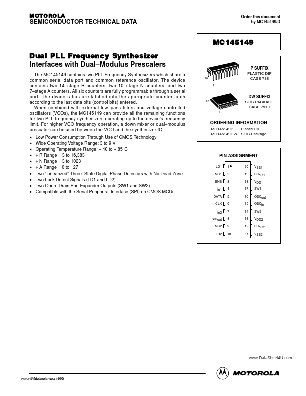
MOTOROLA SEMICONDUCTOR TECHNICAL DATA Order this document by MC145149/D MC145149 Dual PLL Frequency Synthesizer Interfaces with Dual–Modulus Prescalers The MC145149 contains two PLL Frequency Synthesizers which share a common serial data port and common reference oscillator. The device contains two 14–stage R counters, two 10–stage N counters, and two 7–stage A counters. All six counters are fully programmable through a serial port. The divide ratios are latched into the appropriate counter latch according to the last data bits (control bits) entered. When combined with external low–pass filters and voltage controlled oscillators (VCOs), the MC145149 can provide all the remaining functions for two PLL frequency synthesizers operating up to the device’s frequency limit.
Published: |