MC33219A Overview
Key Specifications
Package: SOP
Operating Voltage: 5 V
Length: 15.4 mm
Width: 7.5 mm
Key Features
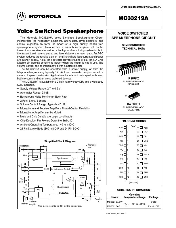
- free speakerphone system. Included are a microphone amplifier with mute, transmit and receive attenuators, a background monitoring system for both the transmit and receive paths, and level detectors for each path. An AGC system reduces the receive gain on long lines where loop current and power are in short supply. A dial tone detector prevents fading of dial tone. A Chip Disable pin permits conserving power when the circuit is not in use. The volume control can be implemented with a potentiometer. The MC33219A can be operated from a power supply, or from the telephone line, requiring typically 3.2 mA. It can be used in conjunction with a variety of speech networks. Applications include not only speakerphones, but intercoms and other voice switched devices. The MC33219A is available in a 24 pin narrow body DIP, and a wide body SOIC package
- Supply Voltage Range: 2.7 to 6.5 V