The following content is an automatically extracted verbatim text
from the original manufacturer datasheet and is provided for reference purposes only.
View original datasheet text
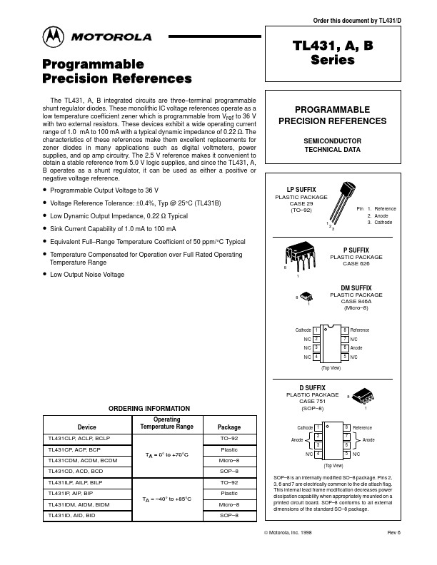
Order this document by TL431/D
TL431, A, B Programmable Precision References
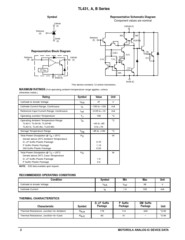
The TL431, A, B integrated circuits are three–terminal programmable shunt regulator diodes. These monolithic IC voltage references operate as a low temperature coefficient zener which is programmable from Vref to 36 V with two external resistors. These devices exhibit a wide operating current range of 1.0 mA to 100 mA with a typical dynamic impedance of 0.22 Ω. The characteristics of these references make them excellent replacements for zener diodes in many applications such as digital voltmeters, power supplies, and op amp circuitry. The 2.5 V reference makes it convenient to obtain a stable reference from 5.
 TL431 Datasheet