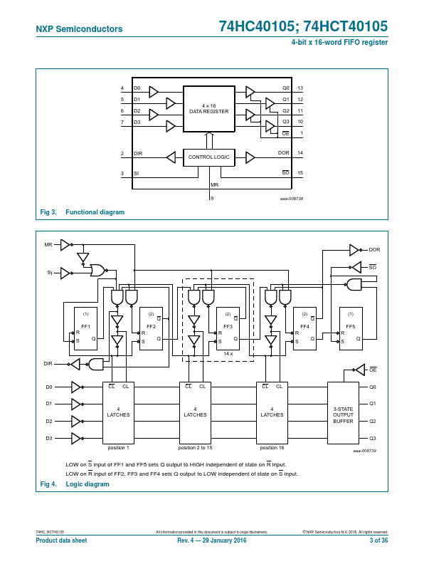
74HCT40105 Description
74HCT40105 is a first-in/first-out (FIFO) "elastic" storage register that can store 16 4-bit words. It can handle input and output data at different shifting rates.
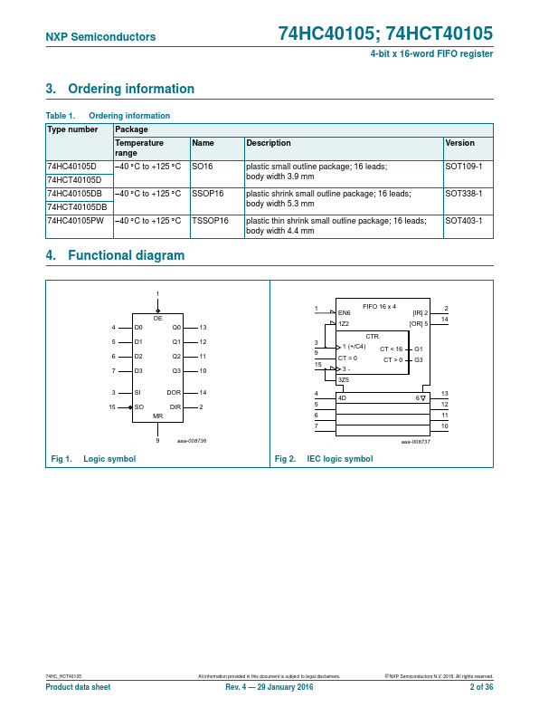
74HCT40105 Key Features
- Independent asynchronous inputs and outputs
- Expandable in either direction
- Reset capability
- Status indicators on inputs and outputs
- 3-state outputs
- Input levels
- For 74HC40105: CMOS level
- For 74HCT40105: TTL level
- 3-state outputs
- plies with JEDEC standard JESD7A