MPC17550 Overview
Key Specifications
Package: SOP
Mount Type: Surface Mount
Pins: 36
Operating Voltage: 3 V
Key Features
- Low Total RDS(ON) 0.7 Ω (Typ), 1.2 Ω (Max) @ 25°C
- Output Current 700 mA (Continuous per Output)
- Shoot-Through Current Protection Circuit
- PWM Control Input Frequency up to 200 kHz
- Built-In DC/DC Boost Converter
- Low Power Consumption Standby Mode
- Undervoltage Detection and Shutdown Circuit
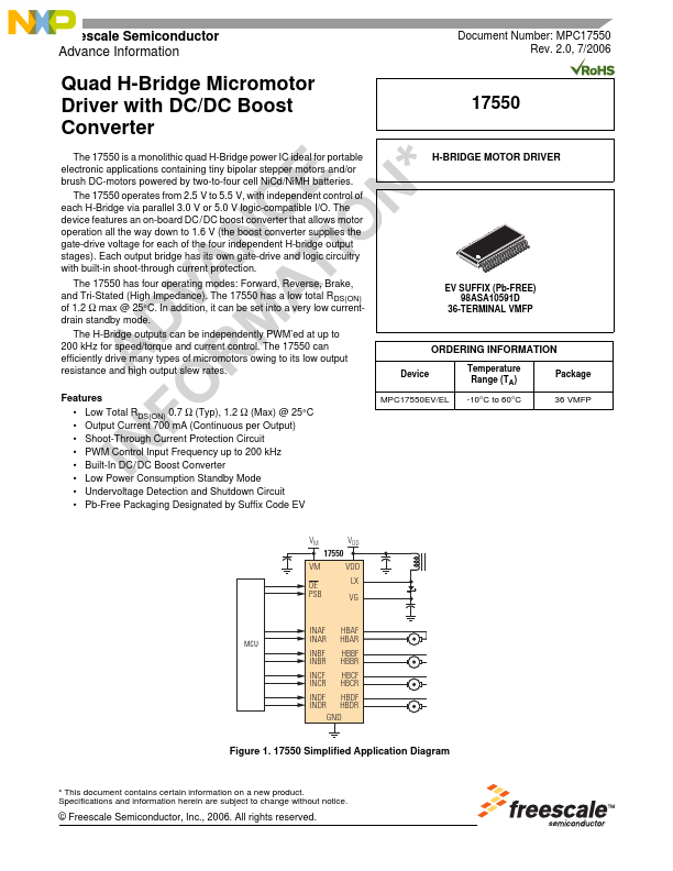
- Pb-Free Packaging Designated by Suffix Code EV H-BRIDGE MOTOR DRIVER EV SUFFIX (Pb-FREE) 98ASA10591D 36-TERMINAL VMFP