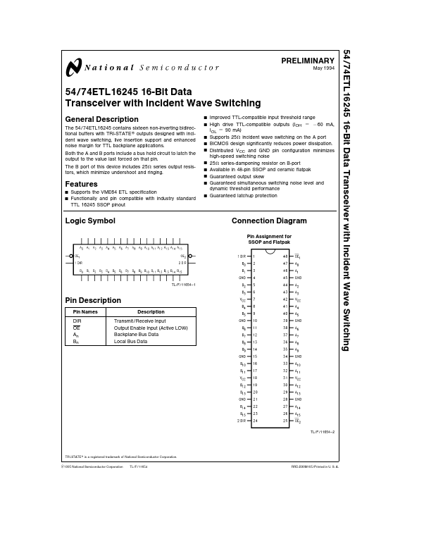
Functional Description
The device uses byte-wide Direction (DIR) control and Out-
put Enable (OE) controls The DIR inputs determine the di-
rection of data flow through the device The OE inputs dis-
able the A and the B ports
The part contains active circuitry which keeps all outputs
disabled when VCC is less than 2 2V to aid in live insertion
applications
Logic Diagrams (Positive Logic)
Truth Table (Each 8-bit Section)
Inputs
OE DIR
LL
LH
HX
Operation
A Data to B Bus
B Data to A Bus
Isolation
TL F 11654–3
ETL’s Improved Noise Immunity
TTL input thresholds are typically determined by tempera-
ture-dependent junction voltages which result in worst case
input thresholds between 0 8V and 2 0V By contrast ETL
provides greater noise immunity because its input thresh-
olds are determined by current mode input circuits similar to
those used for ECL or BTL ETL’s worst case input thresh-
olds between 1 4V and 1 6V are compensated for temper-
ature voltage and process variations
TL F 11654 – 4
Incident Wave Switching
When TTL logic is used to drive fully loaded backplanes the
combination of low backplane bus characteristic imped-
ance wide TTL input threshold range and limited TTL drive
generally require multiple waveform reflections before a val-
id signal can be received across the backplane The VME
International Trade Association (VITA) defined ETL to pro-
vide incident wave switching which increases the data trans-
fer rate of a VME backplane and extends the life of VME
applications TTL compatibility with existing VME back-
planes and modules was maintained
Improved Input Threshold Characteristics of ETL
ABTC Worst Case VOUT – VIN
TL F 11654–5
ETL Worst Case VOUT – VIN
TL F 11654 – 6
2