MCR12M
MCR12M is Silicon Controlled Rectifiers manufactured by onsemi.
MCR12D, MCR12M, MCR12N
Preferred Device
Silicon Controlled Rectifiers
Reverse Blocking Thyristors
Designed primarily for half-wave ac control applications, such as motor controls, heating controls, and power supplies; or wherever half- wave silicon gate- controlled devices are needed.
- Blocking Voltage to 800 Volts
- On- State Current Rating of 12 Amperes RMS at 80°C
- High Surge Current Capability
- 100 Amperes
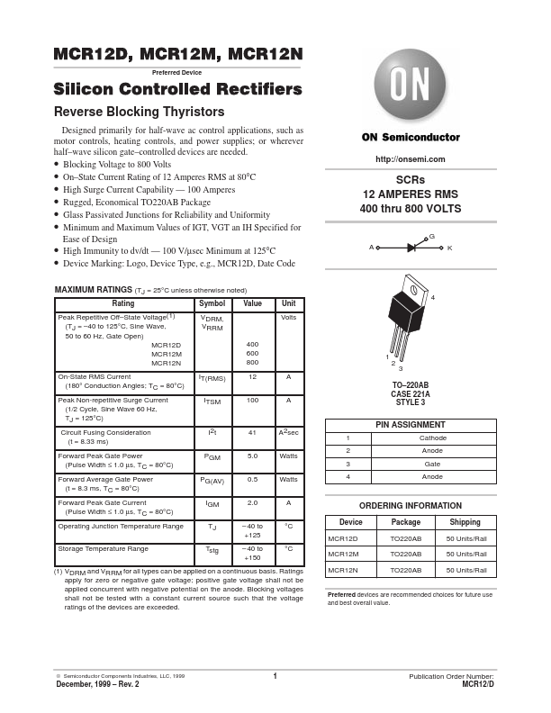
- Rugged, Economical TO220AB Package
- Glass Passivated Junctions for Reliability and Uniformity
- Minimum and Maximum Values of IGT, VGT an IH Specified for Ease of Design
- High Immunity to dv/dt
- 100 V/µsec Minimum at 125°C
- Device Marking: Logo, Device Type, e.g., MCR12D, Date Code
MAXIMUM RATINGS (TJ = 25°C unless otherwise noted)
Rating Peak Repetitive Off- State Voltage(1) (TJ =
- 40 to 125°C, Sine Wave, 50 to 60 Hz, Gate Open) MCR12D MCR12M MCR12N On-State RMS Current (180° Conduction Angles; TC = 80°C) Peak Non-repetitive Surge Current (1/2 Cycle, Sine Wave 60 Hz, TJ = 125°C) Circuit Fusing Consideration (t = 8.33 ms) Forward Peak Gate Power (Pulse Width ≤ 1.0 µs, TC = 80°C) Forward Average Gate Power (t = 8.3 ms, TC = 80°C) Forward Peak Gate Current (Pulse Width ≤ 1.0 µs, TC = 80°C) Operating Junction Temperature Range Storage Temperature Range Symbol VDRM, VRRM 400 600 800 IT(RMS) ITSM 12 100 A A TO- 220AB CASE 221A STYLE 3 Value Unit Volts http://onsemi.
SCRs 12 AMPERES RMS 400 thru 800 VOLTS
I2t PGM PG(AV) IGM TJ Tstg
41 5.0 0.5 2.0
- 40 to +125
- 40 to +150
A2sec Watts Watts A °C °C
PIN ASSIGNMENT
1 2 3 4 Cathode Anode Gate Anode
ORDERING INFORMATION
Device MCR12D MCR12M MCR12N Package TO220AB TO220AB TO220AB Shipping 50 Units/Rail 50 Units/Rail 50 Units/Rail
(1) VDRM and VRRM for all types can be applied on a continuous basis. Ratings apply for zero or negative gate voltage; positive gate voltage shall not be applied concurrent with negative potential on the anode. Blocking voltages shall not be tested with a...