FGH20N60UFD Overview
Key Specifications
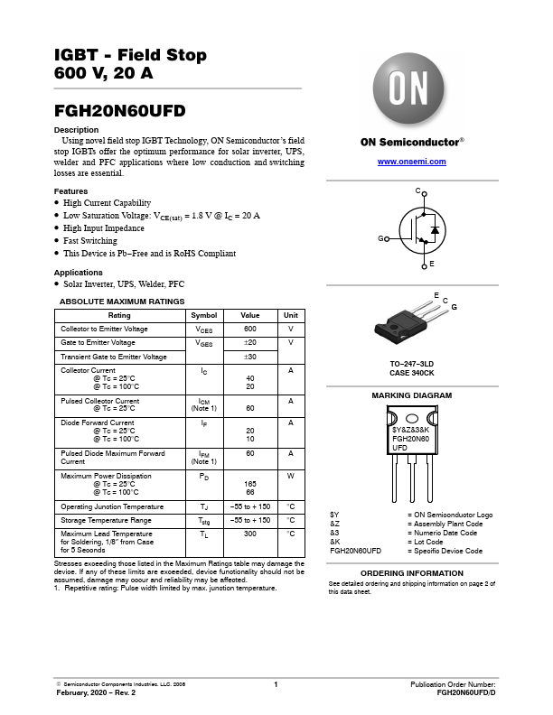
Package: TO-247
Mount Type: Through Hole
Pins: 3
Height: 20.6 mm
Description
Using novel field stop IGBT Technology, ON Semiconductor’s field stop IGBTs offer the optimum performance for solar inverter, UPS, welder and PFC applications where low conduction and switching losses are essential.
Key Features
- High Current Capability
- Low Saturation Voltage: VCE(sat) = 1.8 V @ IC = 20 A
- High Input Impedance
- Fast Switching
- This Device is Pb-Free and is RoHS Compliant