Datasheet4U Logo Datasheet4U.com

FPF2702 - AccuPower 0.4A ~ 2A Adjustable Over-Current Protection Load Switches

Download the FPF2702 datasheet PDF. This datasheet also covers the FPF2700 variant, as both devices belong to the same accupower 0.4a ~ 2a adjustable over-current protection load switches family and are provided as variant models within a single manufacturer datasheet.

General Description

The AccuPower FPF270X series is a family of current

switches that provide full protection to systems and loads from excess current conditions.

Minimum current limit is adjustable from 0.4 A to 2.0 A.

rate controlled N channel MOS

Key Features

  • 2.8 V to 36 V Input Voltage Range.
  • Typical RDS(ON) = 88 mW.
  • 0.4 A to 2 A Adjustable Current Limit (Min. ).
  • Slew Rate Controlled.
  • ESD Protected, Above 2000 V HBM.
  • Thermal Shutdown.
  • Active LOW Enable.
  • UVLO Protection.
  • Power.
  • Good Output.
  • These are Pb.
  • Free Devices Top View Bottom View WDFN8 3x3, 0.65P MLP CASE 511DD Top View SOIC8 SO8 CASE 751EB.

📥 Download Datasheet

Note: The manufacturer provides a single datasheet file (FPF2700-ONSemiconductor.pdf) that lists specifications for multiple related part numbers.

Datasheet Details

Part number FPF2702
Manufacturer onsemi
File Size 1.12 MB
Description AccuPower 0.4A ~ 2A Adjustable Over-Current Protection Load Switches
Datasheet download datasheet FPF2702 Datasheet

Full PDF Text Transcription (Reference)

The following content is an automatically extracted verbatim text from the original manufacturer datasheet and is provided for reference purposes only.

View original datasheet text
DATA SHEET www.onsemi.com 
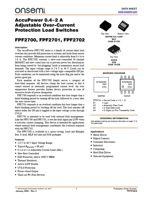
AccuPower 0.4~2 A Adjustable Over-Current Protection Load Switches FPF2700, FPF2701, FPF2702 Description The AccuPower FPF270X series is a family of current−limit load switches that provide full protection to systems and loads from excess current conditions. Minimum current limit is adjustable from 0.4 A to 2.0 A. The FPF270X contains a slew−rate−controlled N−channel MOSFET and slew−rated turn−on to prevent power bus disturbances from being caused by “hot plugging” loads or momentary excess load demands. The input voltage range is 2.8 V to 36 V. Loads can be activated or deactivated with a low−voltage logic−compatible ON pin. Fault conditions can be monitored using the error flag pin and/or the power−good pin.