MCR12DSN
MCR12DSN is Sensitive Gate Silicon Controlled Rectifiers Reverse Blocking Thyristors manufactured by onsemi.
- Part of the MCR12DSM comparator family.
- Part of the MCR12DSM comparator family.
..
MCR12DSM, MCR12DSN
Preferred Device
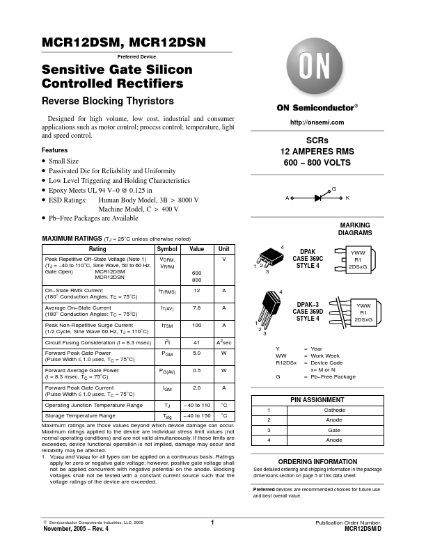
Sensitive Gate Silicon Controlled Rectifiers
Reverse Blocking Thyristors
Designed for high volume, low cost, industrial and consumer applications such as motor control; process control; temperature, light and speed control.
Features http://onsemi.
- -
- -
- -
Small Size Passivated Die for Reliability and Uniformity Low Level Triggering and Holding Characteristics Epoxy Meets UL 94 V- 0 @ 0.125 in ESD Ratings: Human Body Model, 3B u 8000 V Machine Model, C u 400 V Pb- Free Packages are Available
SCRs 12 AMPERES RMS 600
- 800 VOLTS
MAXIMUM RATINGS (TJ = 25°C unless otherwise noted)
Rating Peak Repetitive Off- State Voltage (Note 1) (TJ =
- 40 to 110°C, Sine Wave, 50 to 60 Hz, Gate Open) MCR12DSM MCR12DSN On- State RMS Current (180° Conduction Angles; TC = 75°C) Average On- State Current (180° Conduction Angles; TC = 75°C) Peak Non-Repetitive Surge Current (1/2 Cycle, Sine Wave 60 Hz, TJ = 110°C) Circuit Fusing Consideration (t = 8.3 msec) Forward Peak Gate Power (Pulse Width ≤ 1.0 msec, TC = 75°C) Forward Average Gate Power (t = 8.3 msec, TC = 75°C) Forward Peak Gate Current (Pulse Width ≤ 1.0 msec, TC = 75°C) Operating Junction Temperature Range Storage Temperature Range Symbol VDRM, VRRM 600 800 IT(RMS) IT(AV) ITSM I2t PGM PG(AV) IGM TJ Tstg 12 7.6 100 41 5.0 0.5 2.0
- 40 to 110
- 40 to 150 A A A A2sec W W G A °C °C Y WW R12DSx 1 2 3 Value Unit V 1 2 3 4 DPAK CASE 369C STYLE 4
MARKING DIAGRAMS
YWW R1 2DSx G
4 DPAK- 3 CASE 369D STYLE 4 YWW R1 2DSx G
= Year = Work Week = Device Code x= M or N = Pb- Free Package
PIN ASSIGNMENT
1 2 3 4 Cathode Anode Gate Anode
Maximum ratings are those values beyond which device damage can occur. Maximum ratings applied to the device are individual stress limit values (not normal operating conditions) and are not valid simultaneously. If these limits are exceeded, device functional operation is not implied, damage may occur and reliability may be affected. 1. VDRM and...