NCS29001
NCS29001 is LED Backlight Driver manufactured by onsemi.
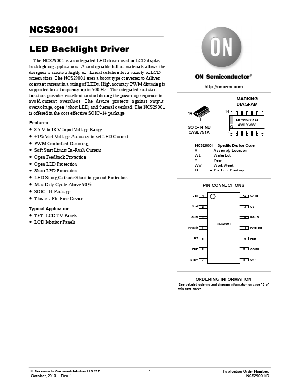
Features http://onsemi. MARKING DIAGRAM
14 1 SOIC- 14 NB CASE 751A 1 14 NCS29001G AWLYWW
- -
- -
- -
- -
- -
- 8.5 V to 18 V Input Voltage Range ±1% Vref Voltage Accuracy to set LED Current PWM Controlled Dimming Soft Start Limits In- Rush Current Open Feedback Protection Open LED Protection Short LED Protection LED String Cathode Short to ground Protection Max Duty Cycle Above 90% SOIC- 14 Package This is a Pb- Free Device
NCS29001= Specific Device Code A = Assembly Location WL = Wafer Lot Y = Year WW = Work Week G = Pb- Free Package
PIN CONNECTIONS
VIN Vref GND PWMin RT FBP STBY 1 2 3 NCS29001 4 5 6 7 11 10 9 8 PWMout FBN P OVP 14 13 12 GATE CS PGND
Typical Application
- TFT- LCD TV Panels
- LCD Monitor Panels
ORDERING INFORMATION
See detailed ordering and shipping information on page 15 of this data sheet.
© Semiconductor ponents Industries, LLC, 2013
October, 2013
- Rev. 1
Publication Order Number: NCS29001/D http://..
Figure 1. Block Diagram http://onsemi.
PINOUT ASSIGNMENT
VIN Vref GND PWMin RT FBP STBY
1 2 3 4 5 6 7 NCS29001
14 13 12 11 10 9 8
GATE CS PGND PMWout FBN P OVP
Figure 2. NSC29001 Pinout
PIN DESCRIPTION
Pin # 1 2 3 4 5 6 7 Symbol VIN VREF GND PWMin RT FBP STBY Type Input Output Ground Output Output Input Input Description
VIN supply input. Small 1.0 m F low ESR bypass capacitor required from VIN to GND. 5 V / 10 m A reference voltage. Small 1.0 m F low ESR bypass capacitor required from VREF to GND. Analog ground. PWM dimming control input. The resistor connected between RT and GND sets the switching frequency The reference voltage for the feedback (FBN). Reference level can be adjusted from 0.5 V up to 3.0 V using an external voltage divider. The converter enters in standby mode when STBY is floating or pulled high. When STBY goes from low to high the circuit will discharge the capacitors on the P pin and keep PWMout high to discharge the output capacitor. STBY must remain high for 50 ms before the part enters...