- Part: 3.0SMCJ10-AU
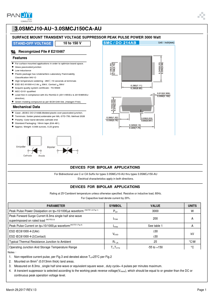
- Description: SURFACE MOUNT TRANSIENT VOLTAGE SUPPRESSOR
- Manufacturer: PanJit Semiconductor
- Size: 365.38 KB
Overview
- For surface mounted applications in order to optimize board space.
- Glass passivated junction
- Low inductance
- Plastic package has Underwriters Laboratory Flammability Classification 94V-O
- High temperature soldering : 260℃/10 seconds at terminals
- ESD IEC-61000-4-2 Air + 30kV, Contact + 30kV
- Acquire quality system certificate : TS16949
- AEC-Q101 qualified
- Lead free in compliance with EU RoHS2.0 (2011/65/EU & 2015/865/EU directive)
- Green molding compound as per IEC61249 Std..(Halogen Free) Mechanical Data
Datasheets by Manufacturer
- 3.0SMCJ10 — Taiwan Semiconductor — Surface Mount Transient Voltage Suppressor
- 3.0SMCJ10 — TIPTEK — 3000W SURFACE MOUNT TRANSIENT VOLTAGE SUPPRESSOR
- 3.0SMCJ10 — Won-Top Electronics — 3000W SURFACE MOUNT TRANSIENT VOLTAGE SUPPRESSOR
- 3.0SMCJ10 — HITANO — Transient Voltage Suppressors
- 3.0SMCJ10 — Bruckewell Technology — SURFACE MOUNT TRANSIENT VOLTAGE SUPPRESSOR
- 3.0SMCJ10 — Good-Ark Semiconductor — Transient Voltage Suppressors
- 3.0SMCJ100 — Taiwan Semiconductor — Surface Mount Transient Voltage Suppressor
- 3.0SMCJ10CA — TIPTEK — 3000W SURFACE MOUNT TRANSIENT VOLTAGE SUPPRESSOR
- 3.0SMCJ100A — Taiwan Semiconductor — Surface Mount Transient Voltage Suppressor
- 3.0SMCJ100 — EIC Semiconductor — SURFACE MOUNT TRANSIENT VOLTAGE SUPPRESSOR