EEEFPC821UAP Overview
Key Specifications
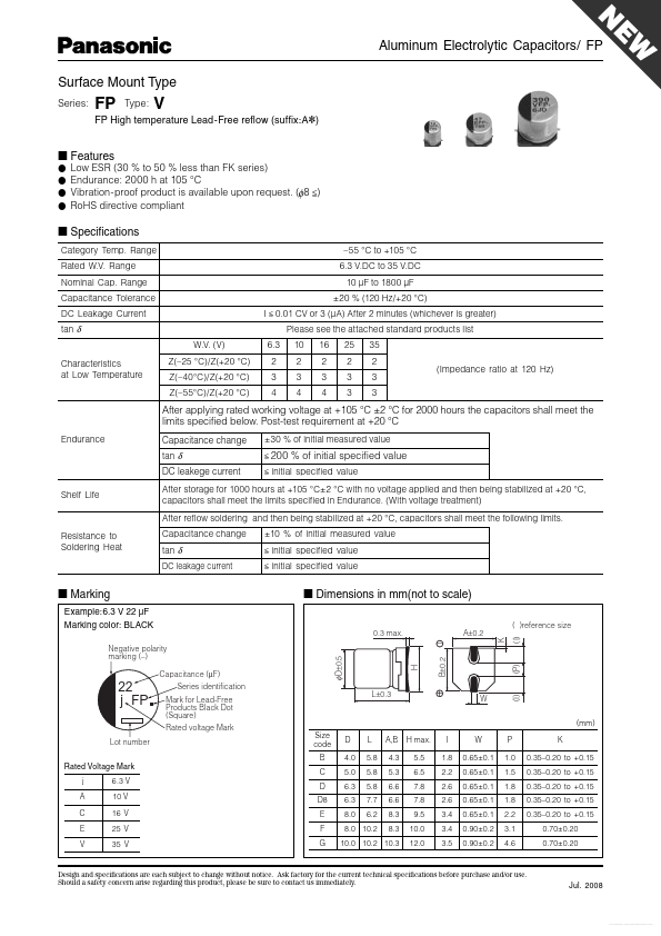
Package: SMD/SMT
Mount Type: Surface Mount
Height: 10.2 mm
Length: 10.2 mm
Key Features
- Marking Example:6.3 V 22 µF Marking color: BLACK
| Part | EEEFPC821UAP |
|---|---|
| Description | Aluminum Electrolytic Capacitors |
| Manufacturer | Panasonic |
| Size | 95.45 KB |
Package: SMD/SMT
Mount Type: Surface Mount
Height: 10.2 mm
Length: 10.2 mm
| Seller | Inventory | Price Breaks | Buy |
|---|---|---|---|
| Verical | 4000 | 500+ : 0.5276 USD 1000+ : 0.4634 USD 2500+ : 0.4273 USD |
View Offer |
| Onlinecomponents.com | 4000 | 500+ : 0.402 USD 1000+ : 0.3596 USD 2500+ : 0.3376 USD 5000+ : 0.3337 USD |
View Offer |
| Part Number | Manufacturer | Description |
|---|---|---|
| SFC37S35-xxxxxE-F | CDE | Iol-Filled Motor Run Capacitors |
| SXCxxxx | Rubycon Corporation | SXC Series / Capacitors |
| C0805Cxxxx | Vishay | Multilayer Ceramic Capacitors |