Datasheet Summary
..
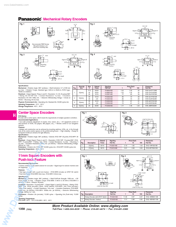
Mechanical Rotary Encoders
Fig. 1
5 0.7 C 5 14 12.4
Signal A 10kΩ 10kΩ A B DC 5V 10kΩ 10kΩ Signal B 0.01μ Encoder
Fig. 2
D.C. 5V
5.5 7 2.0 7.5 3.5 M9 P=0.75 1.0 Mounting Surface C
10k Signal A 0.01µ
10k A B Encoder Block
10k
Signal B 0.01µ
12.4 A B 13.2 2-2.1 2-2 7.5 5 3-Ø1
0.01μ
13.2 2-2.0 7.5 5 2-2.1 Cntr. of shaft 3
- Ø1.0
Remended PWB Piercing Plan pitch tolerance: ±0.1 (view from mounting side)
Center of shaft
Fig. 3
5.5 7 2.0 7.5 3.5
10k Signal A 0.01µ
D.C. 5V 10k A B Encoder Block 10k
Fig. 4
C 5.0 7.0
D.C. 5V 10k Signal A 0.01µ 10k A B Encoder Block
Signal B 0.01µ
7.0 7.5 3.65 Mounting Surface
10k
Signal...