K3637 Description
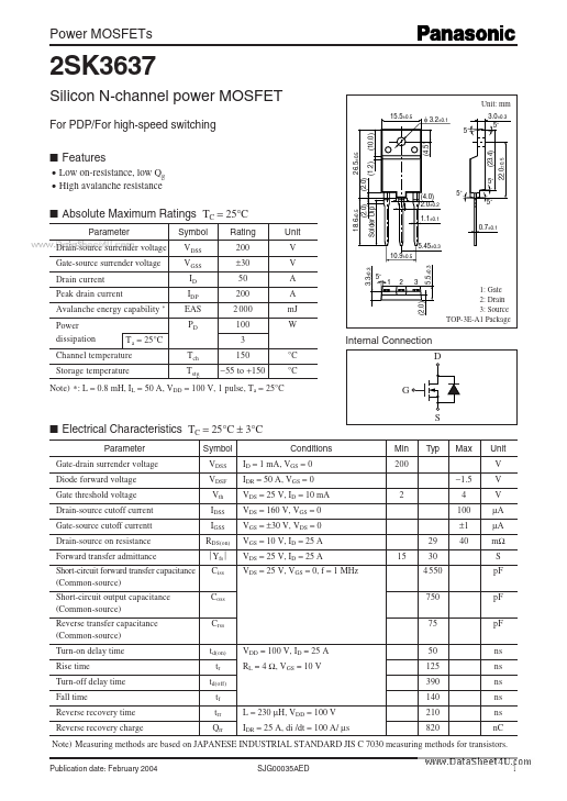
Power MOSFETs 2SK3637 Silicon N-channel power MOSFET 15.5±0.5 Unit: Source TOP-3E-A1 Package Internal Connection Channel temperature Storage temperature (2.0) D G S Note) : February 2004 SJG00035AED 22.0±0.5 (1.2).
K3637 Key Features
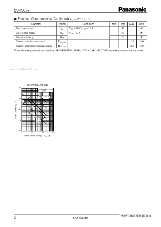
- Electrical Characteristics (Continued) TC = 25°C ± 3°C