PA4344.562NLT
PA4344.562NLT is SMT Power Inductors manufactured by Pulse.
- Part of the PA4344.102NLT comparator family.
- Part of the PA4344.102NLT comparator family.
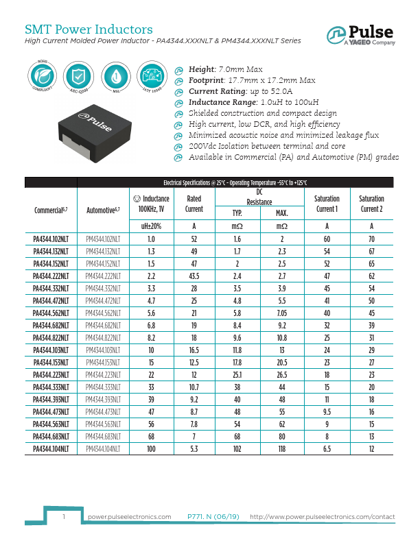
SMT Power Inductors
High Current Molded Power Inductor
- PA4344.XXXNLT & PM4344.XXXNLT Series
Height: 7.0mm Max Footprint: 17.7mm x 17.2mm Max Current Rating: up to 52.0A Inductance Range: 1.0u H to 100u H Shielded construction and pact design High current, low DCR, and high efficiency Minimized acoustic noise and minimized leakage flux 200Vdc Isolation between terminal and core Available in mercial (PA) and Automotive (PM) grades mercial6,7
Automotive6,7
PA4344.102NLT PA4344.132NLT PA4344.152NLT PA4344.222NLT PA4344.332NLT PA4344.472NLT PA4344.562NLT PA4344.682NLT PA4344.822NLT PA4344.103NLT PA4344.153NLT PA4344.223NLT PA4344.333NLT PA4344.393NLT PA4344.473NLT PA4344.563NLT PA4344.683NLT PA4344.104NLT
PM4344.102NLT PM4344.132NLT PM4344.152NLT PM4344.222NLT PM4344.332NLT PM4344.472NLT PM4344.562NLT PM4344.682NLT PM4344.822NLT PM4344.103NLT PM4344.153NLT PM4344.223NLT PM4344.333NLT PM4344.393NLT PM4344.473NLT PM4344.563NLT PM4344.683NLT PM4344.104NLT
Electrical Specifications @ 25°C
- Operating Temperature -55°C to +125°C
Inductance 100KHz, 1V
Rated Current
DC Resistance
TYP. MAX.
Saturation Current 1 u H±20%
A mΩ mΩ
1.0 52 1.6 2 60
1.3 49 1.7 2.3 54
1.5 47 2 2.5 52
2.2 43.5 2.4 2.7 47
3.3 28 3.5 3.9 45
4.7 25 4.8 5.5
5.6 21 5.8 7.05 40
6.8 19 8.4 9.2
8.2 18 9.6 10.8 25
10 16.5 11.8
15 12.5 17.8 20.5
22 12 25.1 26.5 18
33 10.7 38 44 15
39 9.2 40 48 11
47 8.7 48 55...