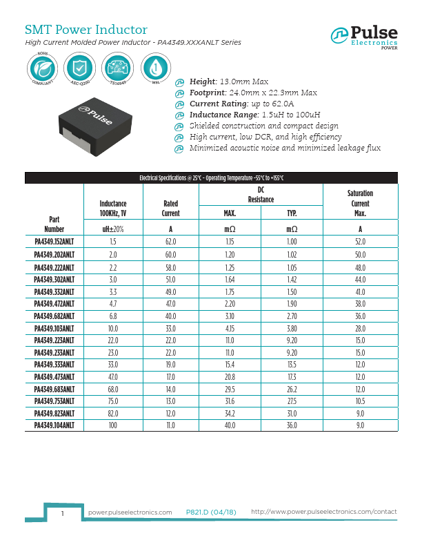
SMT Power Inductor
High Current Molded Power Inductor - PA4349.XXXANLT Series
Notes:
1. Actual temperature of the component during system operation (ambient plus tempera- 3. The rated current is the DC current required to raise the component temperature by
ture rise) must be within the standard operating range.
approximately 40�C. Take note that the components’ performanc varies depending on the
2. The saturation current is the current at which the initial inductance drops approxi-
system condition. It is suggested that the component be tested at the system level, to
mately 30% at the stated ambient temperature. This current is determined by placing verify the temperature rise of the component during system operation.
the component in the specified ambient environment and applying a short duration 4. The part temperature (ambient+temp rise) should not exceed 155�C under worst case
pulse current (to eliminate self-heating effect) to the component.
operating conditions. Circuit design, PCB trace size and thickness, airflow and other cool-
ing provisions all affect the part temperature. Part temperature should be verified in the
end application.
PA4349.XXXANLT
A
Mechanical
CD
B
XXXANL
D/C
E
Series
PA4349.XXXANLT
All Dimensions in mm.
A
23.5±0.5
TAPE & REEL INFO
Final Layout
B
22.0±0.3
C
12.6±0.4
D
5.0±0.4
E
19.0±0.3
Blank portions
Chip cavity
Blank portions
L
G
SUGGESTED PAD LAYOUT
LG
24 12.5
H
19.6
K0
P1
200mm or more
Direction of tape
400mm or more
G
PA4349.XXXANLT
SURFACE MOUNTING TYPE, REEL/TAPE LIST
REEL SIZE (mm)
TAPE SIZE (mm)
A G P1 W K0
Ø330 44.4+2/-0 32±0.1 44±0.3 13±0.1
QTY
PCS/REEL
120
2 power.pulseelectronics.com P821.D (04/18) http://www.power.pulseelectronics.com/contact