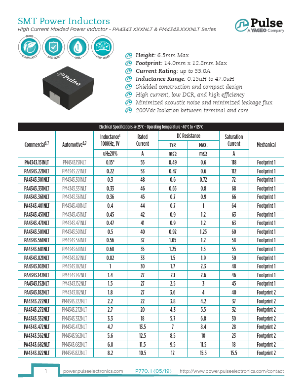
SMT Power Inductors
High Current Molded Power Inductor - PA4343.XXXNLT & PM4343.XXXNLT Series
Commercial6,7
PA4343.103NLT
PA4343.133NLT
PA4343.153NLT
PA4343.223NLT
PA4343.333NLT
PA4343.473NLT
Automotive6,7
PM4343.103NLT
PM4343.133NLT
PM4343.153NLT
PM4343.223NLT
PM4343.333NLT
PM4343.473NLT
Electrical Specifications @ 25°C - Operating Temperature -40°C to +125°C
Inductance
100KHz, 1V
Rated
Current
DC Resistance
TYP. MAX.
uH±20% A mΩ mΩ
10 10 13.2 16.5
13 9 21 24
15 9 23.2 28
22 9 32.5 37
33 8 48 58
47 6.5 76 90
Saturation
Current
A
15.5
13
12.5
12
11
9.5
Mechanical
Footprint 2
Footprint 2
Footprint 2
Footprint 2
Footprint 2
Footprint 2
Notes:
1. Actual temperature of the component during system operation (ambient plus
other cooling provisions all affect the part temperature. Part temperature should be
temperature rise) must be within the standard operating range.
verified in the end application.
2. The saturation current is the current at which the initial inductance drops approxi- 5. Please note that the inductance tolerance of all parts are ±20%, except .151NLT which
mately 30% at the stated ambient temperature. This current is determined by placing
is ±30%.
the compnent in the specified ambient environment and applying a short duration 6. Parts shown in bold are standard catalog parts and are available through sample
pulse current (to eliminate self-heating effect) to the component.
stock and distribution. Parts in lighter font are available but are not necessarily held
3. The rated current is the DC current required to raise the component temperature by
in sample stock or distribution and lead times may be longer. Please contact Pulse
approximately 40�C. Take note that the components’ performanc varies depending
for availablity.
on the system condition. It is suggested that the component be tested at the system 7. The PA4343.XXXNLT and PM4343.XXXNLT are both AEC-Q200 qualified. The PM4546.
level, to verify the temperature rise of the component during system operation.
XXXNLT part numbers are also IATF16949 certified. The mechanical dimensions are
4. The part temperature (ambient+temp rise) should not exceed 125�C under worst
100% tested in production but do not necessarily meet a product capability index
case operating conditions. Circuit design, PCB trace size and thickness, airflow and
(Cpk) 1.33 and therefore the PM4546.XXXNLT may not strictly conform to PPAP.
Mechanical
PA4343/PM4343
Final Layout
SUGGESTED PAD LAYOUT
Series Mechanical A B C D E F G H
PA4343/PM4343 Footprint 1
14.0 Max
12.8 Max
6.5 Max
(4.0)
(8.9)
(4.3)
(3.1)
(8.0)
PA4343/PM4343 Footprint 2
14.0 Max
12.8 Max
6.5 Max
(4.7)
(8.9)
(5.0)
(3.1)
(8.0)
All Dimensions in mm.
2
power.pulseelectronics.com
P770. I (05/19) http://www.power.pulseelectronics.com/contact