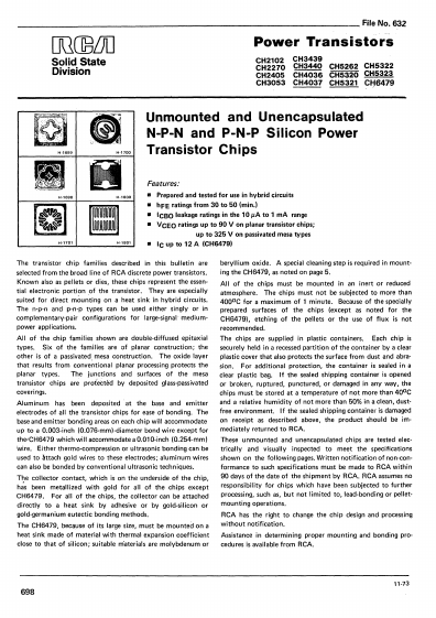
_ _~_ _ _ _ _ _ _ _ _ _ _ _ _ _ _ _ _ _ _ _ _ _ _ _ _ _ _ _ FileNo. 632
OOCD5LJO
Solid State
Division
Power Transistors
CH2102 CH3439
CH2270 CH3440 CH5262 CH5322
CH2405 CH4036 CH5320 CH5323
CH3053 CH4037 CH5321 CI-!6479
Unmounted and Unencapsulated
N-P-N and P-N-P Silicon Power
Transistor Chips
Features:
• Prepared and tested for use in hybrid qircuits
• hFE ratings from 30 to 50 (min.)
• ICBO leakage ratings in the 10 IlA to 1 mA range
• VCEO ratings up to 90 V on planar transistor chips;
up to 325 V on passivated mesa ty pes
H-1B01
• IC up to 12 A (CH6479)
The transistor chip families described in this bulletin are
selected from the broad line of RCA discrete power transistors.
Known also as pellets or dies. these chips represent the essen·
tial electronic portion of the transistor. They are especially
suited for direct mou~ting on a heat sink in hybrid circuits.
The n·p·n and p·n·p types can be used either singly or in
complementary·pair configurations for large·signal' medium·
power applications.
All of the chip families shown are double·diffused epitaxial
types. Six of the families are of planar construction; the
other is of a passivated, mesa construction, The oxide layer
that results from conventional planar processing protects the
planar types. The junctions and surfaces of the mesa
transistor chips are protebted by deposited glass·passivated
coverings.
Aluminum has been deposited at the base and emitter
electrodes of all the transistor chips for ease of bonding, The
base and emitter bonding areas on each chip will accommodate
up to a 0.003·inch (0.076·mm)·diameter bond wire except for
the'CH6479 which will accommodate a O,OIO·inch (0.254·mm)
wire. Either thermo·compression or ultrasonic bonding can be
used to Attach gold wires to these electrodes; aluminum wires
can also be bonded by conventional ultrasonic techniques.
T~e collector contact, which is on the underside of the chip,
has been metallized with gold for all of the chips except
CH6479. For all of the chips, the collector can be attached
directly to a heat sink by adhesive or by gold'silicon or
gold·germanium eutectic bonding methods.
The CH6479, because of its large size, must be mounted on a
heat sink made of material with thermal expansion coefficient
close to that of silicon; suitable materials are molybdenum or
beryllium oxide. A special cleaning step is required in mount·
ing the CH6479, as noted on page 5,
All of the chips must be mounted in an inert or reduced
atmosphere, The chips must not be subjected to more than
4000 C for a maximum of I minute. Because of the specially
prepared surfaces of the chips (except as noted for the
CH6479), etching of the pellets or the use of flux is not
recommended.
The chips are supplied in plastic containers. Each chip is
securely held in a recessed partition of the container by a clear
plastic cover that also protects the surface from dust and abra·
sian. For additional protection, the container is sealed in a
clear plastic bag. If the sealed shipping container is opened
or broken, ruptured, punctured, or damaged in any way, the
chips must be stored at a temperature of not more than 400 C
and a relative humidity of not more than 50% in a clean, dust·
free environment. If the sealed shipping container is damaged
on receipt as described above, the product should be im·
mediately returned to RCA.
These unmounted and unencapsulated chips are tested elec·
trically and visually inspected to meet the specifications
shown on the following pages. Written notification of non·con·
formance to such specifications must be made to RCA within
90 days of the date of the shipment by RCA. RCA assumes no
responsibility for chips which have been subjected to further
processing, such as, but not limited to, lead·bonding or pellet·
mounting operations.
RCA has the right to change the chip design and processing
without notification.
Assistance in determining proper mounting and bonding pro·
cedures is available from RCA.
11·73
698