2SCR574D3FRA
Key Features
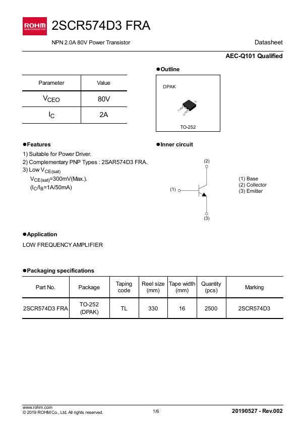
- plementary PNP Types : 2SAR574D3 FRA
- Low VCE(sat) VCE(sat)=300mV(Max.). (IC/IB=1A/50mA) lInner circuit Datasheet AEC-Q101 Qualified
| Part Number | Manufacturer | Description |
|---|---|---|
| 2SCR574D | Inchange Semiconductor | Silicon NPN Power Transistor |