DTA123YCAHZG Description
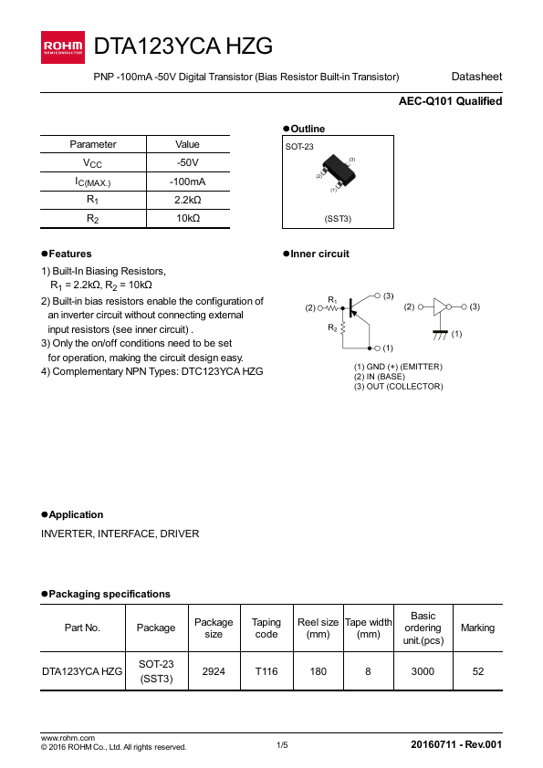
3) Only the on/off conditions need to be set for operation, making the circuit design easy. DTC123YCA HZG lOutline SOT-23 (SST3) lInner circuit lApplication INVERTER, INTERFACE, DRIVER lPackaging specifications Part No. Package DTA123YCA HZG SOT-23 (SST3) Package size 2924 Taping code Reel size Tape width (mm) (mm) Basic ordering unit.(pcs) Marking T116 180 8 3000.