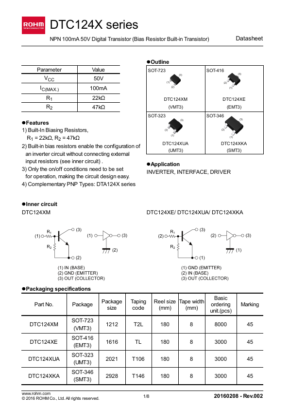
Download the DTC124XM datasheet PDF.
This datasheet also covers the DTC124XUA variant, as both devices belong to the same digital transistors family and are provided as variant models within a single manufacturer datasheet.
Key Features
1) Built-In Biasing Resistors, R1 = 22kΩ, R2 = 47kΩ 2) Built-in bias resistors enable the configuration of an inverter circuit without connecting external input resistors (see inner circuit) . 3) Only the on/off conditions need to be set for operation, making the circuit design easy. 4) Complementary PNP Types: DTA124X series
lOutline
SOT-723
SOT-416
DTC124XM (VMT3)
SOT-323
DTC124XE (EMT3)
SOT-346
DTC124XUA (UMT3)
DTC124XKA (SMT3)
l.
Full PDF Text Transcription for DTC124XM (Reference)
Note: Below is a high-fidelity text extraction (approx. 800 characters) for
DTC124XM. For precise diagrams, and layout, please refer to the original PDF.
DTC124X series NPN 100mA 50V Digital Transistor (Bias Resistor Built-in Transistor) Datasheet Parameter VCC IC(MAX.) R1 R2 Value 50V 100mA 22kΩ 47kΩ lFeatures 1) Built-In...
View more extracted text
ter VCC IC(MAX.) R1 R2 Value 50V 100mA 22kΩ 47kΩ lFeatures 1) Built-In Biasing Resistors, R1 = 22kΩ, R2 = 47kΩ 2) Built-in bias resistors enable the configuration of an inverter circuit without connecting external input resistors (see inner circuit) . 3) Only the on/off conditions need to be set for operation, making the circuit design easy. 4) Complementary PNP Types: DTA124X series lOutline SOT-723 SOT-416 DTC124XM (VMT3) SOT-323 DTC124XE (EMT3) SOT-346 DTC124XUA (UMT3) DTC124XKA (SMT3) lApplication INVERTER, INTERFACE, DRIVER lInner circuit DTC124XM DTC124XE/ DTC124XUA/ DTC124XKA lPackaging specifications Part No.