P85NF55
Description
These Power MOSFETs have been developed using STMicroelectronics’ unique STripFET process, which is specifically designed to minimize input capacitance and gate charge.
Key Features
- AEC-Q101 qualified
- Exceptional dv/dt capability
- 100% avalanche tested
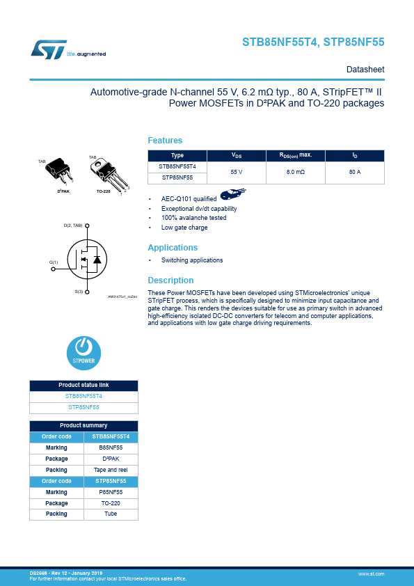
- Low gate charge RDS(on) max. 8.0 mΩ ID 80 A G(1) S(3)