STPS10L40C
STPS10L40C is Low drop power Schottky rectifier manufactured by STMicroelectronics.
Low drop power Schottky rectifier
- production data
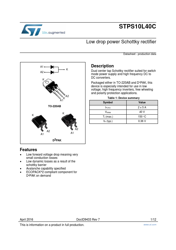
A1 K
A2
A2 K A1 TO-220AB KK
A2 A1
D2PAK
A2 A1
Features
- Low forward voltage drop meaning very small conduction losses
- Low dynamic losses as a result of the schottky barrier
- Avalanche capability specified
- ECOPACK®2 pliant ponent for
D²PAK on demand
Description
Dual center tap Schottky rectifier suited for switch mode power supply and high frequency DC to DC converters.
Packaged either in TO-220AB and D2PAK, this device is especially intended for use in low voltage, high frequency inverters, free wheeling and polarity protection applications.
Table 1: Device summary
Symbol
Value
IF(AV) VRRM Tj (max.) VF (typ.)
2x5A 40 V
150 °C 0.36 V
April 2016
Doc ID9433 Rev 7
This is information on a product in full production.
1/12
.st.
Characteristics
1 Characteristics...