Datasheet4U Logo Datasheet4U.com

STPS640 Datasheet POWER SCHOTTKY RECTIFIER

Manufacturer: STMicroelectronics

General Description

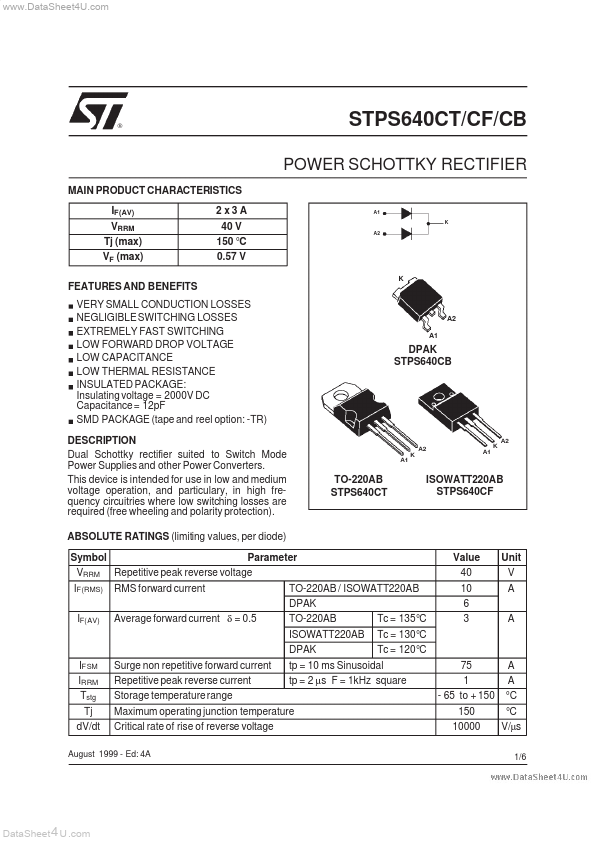
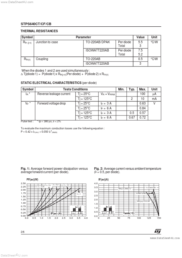
Dual Schottky rectifier suited to Switch Mode Power Supplies and other Power Converters.

This device is intended for use in low and medium voltage operation, and particulary, in high frequency circuitries where low switching losses are required (free wheeling and polarity protection).

ABSOLUTE RATINGS (limiting values, per diode) Symbol VRRM IF(RMS) IF(AV) RMS forward current Average forward current δ = 0.5 Parameter Repetitive peak reverse voltage TO-220AB / ISOWATT220AB DPAK TO-220AB ISOWATT220AB DPAK IFSM IRRM Tstg Tj dV/dt Surge non repetitive forward current Repetitive peak reverse current Storage temperature range Critical rate of rise of reverse voltage Tc = 135 °C Tc = 130 °C Tc = 120 °C 75 1 - 65 to + 150 150 10000 A A °C °C V/µs 1/6 2 x3A 40 V 150 °C 0.57 V A1 K A2 K A2 A1 DPAK STPS640CB A1 K A2 A1 K A2 TO-220AB STPS640CT ISOWATT220AB STPS640CF Value 40 10 6 3 Unit V A A tp = 10 ms Sinusoidal tp = 2 µs F = 1kHz square Maximum operating junction temperature August 1999 - Ed: 4A DataSheet 4 U .com www.DataSheet4U.com STPS640CT/CF/CB THERMAL RESISTANCES Symbol Rth (j-c) Junction to case Parameter TO-220AB/ DPAK ISOWATT220AB Rth(c) Coupling TO-220AB ISOWATT220AB Per diode Total Per diode Total Value 5.5 3 7.5 5.2 0.5 3 Unit °C/W °C/W When the diodes 1 and 2 are used simultaneously: ∆ Tj(diode 1) = P(diode1) x Rth(j-c)(Per diode) + P(diode 2) x Rth(c) STATIC ELECTRICAL CHARACTERISTICS (per diode) Symbol IR * VF * Tests Conditions Reverse leakage current Forward voltage drop Tj = 25°C Tj = 125°C Tj = 25°C Tj = 25°C Tj = 125°C Tj = 125

Overview

www.DataSheet4U.com ® STPS640CT/CF/CB POWER SCHOTTKY RECTIFIER MAIN PRODUCT CHARACTERISTICS IF(AV) VRRM Tj (max) VF.

Key Features

  • VERY SMALL.