ERA15-08 Description
ERA15-01 ERA15-10 PLASTIC SILICON RECTIFIER DIODES VOLTAGE RANGE:.
ERA15-08 Key Features
- 65 to +125
- 65 to +150
ERA15-08 is PLASTIC SILICON RECTIFIER DIODES manufactured by SUNMATE.
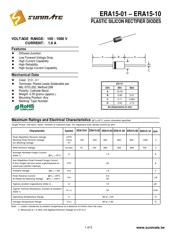
ERA15-01 ERA15-10 PLASTIC SILICON RECTIFIER DIODES VOLTAGE RANGE:.