HRLU150N10K Description
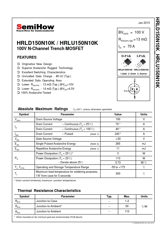
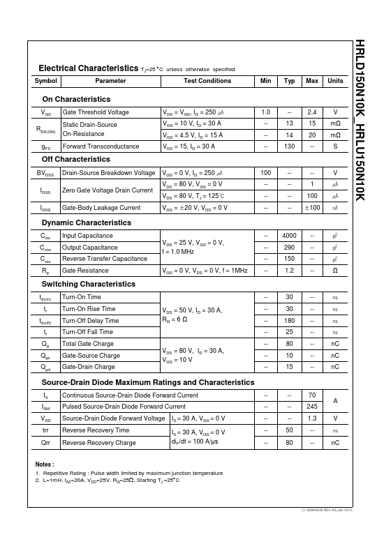
HRLD150N10K_HRLU150N10K HRLD150N10K / HRLU150N10K 100V N-Channel Trench MOSFET.
HRLU150N10K is N-Channel MOSFET manufactured by SemiHow.
| Part Number | Description |
|---|---|
| HRLU120N10H | N-Channel Trench MOSFET |
| HRLU125N06K | N-Channel MOSFET |
| HRLU1B8N10K | N-Channel MOSFET |
| HRLU370N10K | N-Channel MOSFET |
| HRLU43N06H | N-Channel Trench MOSFET |
HRLD150N10K_HRLU150N10K HRLD150N10K / HRLU150N10K 100V N-Channel Trench MOSFET.