LT140A
LT140A is Hall Voltage 160mV Thin-Type Package GaAs Hall Device manufactured by Sharp Corporation.
Features
¡Small temperature coefficient of the Hall voltage ¡Good linearity of the Hall voltage ¡Small imbalanced voltage ¡Directly DC voltage applicable s Applications ¡Brushless motors VCR, CD, CD-ROM, FDD ¡Measuring equipment Gauss meters, magnetic substance detectors ¡Noncontact sensors Microswitches, tape-end detection ¡Other magnetic detection
0.3 1
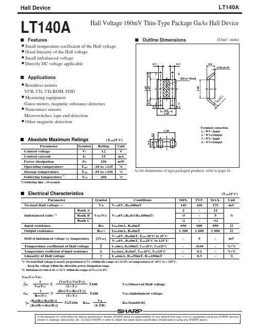
0.3 4 Silver Mark
0.6 0.05±0.05
2.45 1.45
2 0.3 0.9 1.45
3 0.3
Parameter Control voltage Control current Power dissipation Operating temperature Storage temperature Soldering temperature- 1
- 1 Soldering time : 10 seconds
Symbol Rating VC 12 IC 15 150 PD -20 to +125 Topr -55 to +150 Tstg 260 Tsol
Unit V m A m W ˚C ˚C ˚C
As for dimensions of tape-packaged products, refer to page 44 . s Electrical Characteristics
Parameter No-load Hall voltage
- 1 Imbalanced ratio
- 2 Input resistance Output resistance Drift of imbalanced voltage vs. temperature Temperature coefficient of Hall voltage Temperature coefficient of input resistance Linearity of Hall voltage Rank A Rank B Rank C Symbol VH VHO/VH RIN ROUT |∆VHO| β α γ Conditions VC=6V, B=100m T VC=6V,(B=0)/(B=100m T) IM=1m A, B=0m T IM=1m A, B=0m T VC=6V, B=0m T, Ta=-20˚C to 25˚C VC=6V, B=0m T, Ta=25˚C to 125˚C IC=6m A, B=100m T, T1=-20˚C, T2=125˚C IM=1m A, B=0m T, T1=-20˚C, T2=125˚C IC=6m A, B1=50m T, B2=100m T MIN. 145 2 -5 -2 650 1 300 TYP. 160 800 1 600 5 -0.04 0.2 0.3 MAX. 175 12 5 -12 950 1 900
- 0.6 0.4 s Absolute Maximum Ratings
(Ta=25˚C)
Terminal connection 1 : + VC Input 2 : + VH Output 3 :
- VC Input 4 :
- VH Output
0.1 4
+ -0 0.1 .04
(Ta=25˚C) Unit m V % Ω Ω m V %/˚C %/˚C %
- 1 No-load Hall voltage is nearly proportional to Vc (within the range of 1 to 6V) at temperatures of -20˚C to + 125˚C. Keep the voltage within the allowable power dissipation range.
- 2 Imbalanced ratio is in +/-12% within the range of Vc=1 to 6V.
VH=VM-VHO 1 {VH(T2)-VH(T1)} β= X100 X VH(T1) (T2-T1) {RIN(T2)-RIN(T1)} 1 X X100 α= (T2-T1) RIN(T1) {KH(B2)-KH(B1)} VH...