Download the MBR1045 datasheet PDF.
This datasheet also covers the MBR1035 variant, as both devices belong to the same 10a schottky barrier rectitier family and are provided as variant models within a single manufacturer datasheet.
General Description
MBR1035 MBR1045 MBR1050 MBR1060 Unit
Conditions
VRRM VDC
Maximum Repetitive Peak Reverse Voltage
Maximum DC Blocking Voltage
35 45 50 60 V 35 45 50 60 V
IF(AV)
Maximum Average Forward Rectified Current
IFSM Peak Forward Surge Current per leg
TJ Operating Junction Temperature Range
10 150 -
Key Features
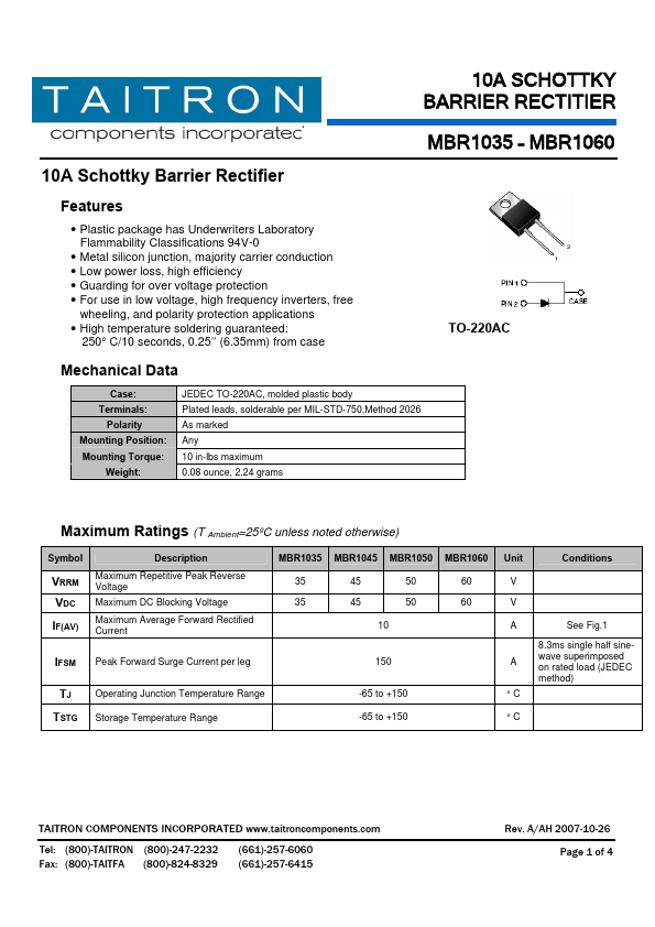
Plastic package has Underwriters Laboratory Flammability Classifications 94V-0.
Metal silicon junction, majority carrier conduction.
Low power loss, high efficiency.
Guarding for over voltage protection.
For use in low voltage, high frequency inverters, free
wheeling, and polarity protection.
Full PDF Text Transcription for MBR1045 (Reference)
Note: Below is a high-fidelity text extraction (approx. 800 characters) for
MBR1045. For precise diagrams, and layout, please refer to the original PDF.
ackage has Underwriters Laboratory Flammability Classifications 94V-0 • Metal silicon junction, majority carrier conduction • Low power loss, high efficiency • Guarding for over voltage protection • For use in low voltage, high frequency inverters, free wheeling, and polarity protection applications • High temperature soldering guaranteed: 250° C/10 seconds, 0.25’’ (6.35mm) from case Mechanical Data Case: Terminals: Polarity Mounting Position: Mounting Torque: Weight: JEDEC TO-220AC, molded plastic body Plated leads, solderable per MIL-STD-750,Method 2026 As marked Any 10 in-lbs maximum 0.08 ounce, 2.