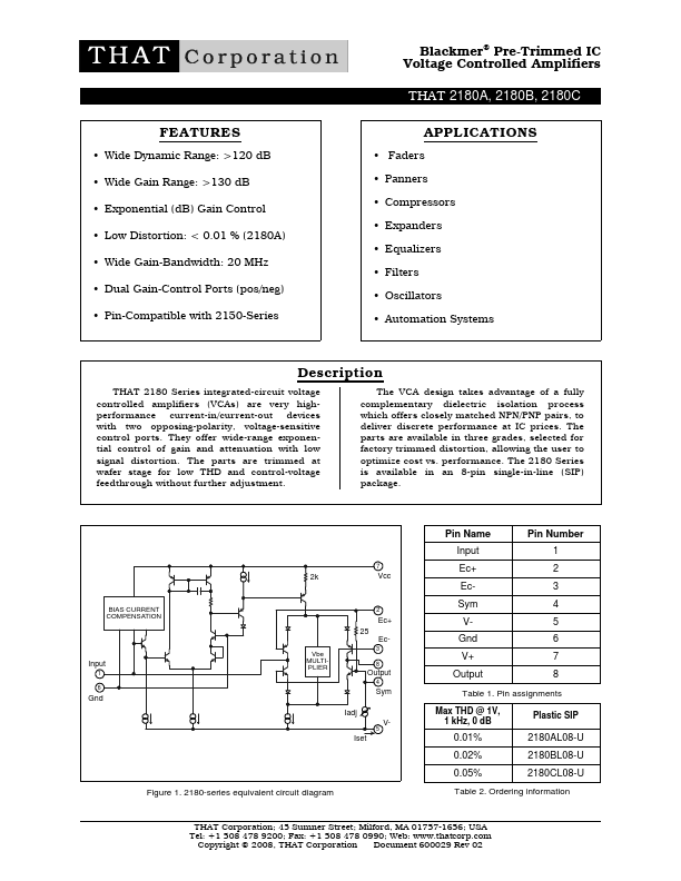
Document 600029 Rev 02
Page 2 of 12
THAT 2180 Series
Blackmer® Pre-trimmed IC VCAs
Positive Supply Voltage (VCC)
Negative Supply Voltage (VEE)
Supply Current (ICC)
Maximum ∆EC EC+ - (EC-)
SPECIFICATIONS1
Absolute Maximum Ratings2,3
+20 V
-20 V
10 mA
±1V
Power Dissipation (PD) (TA = 75 ºC)
Operating Temperature Range (TOP)
Storage Temperature Range (TST)
330 mW
0 to +70 ºC
-40 to +125 ºC
Parameter
Recommended Operating Conditions
Symbol
Conditions
2180A
2180B
Min Typ Max Min Typ Max
2180C
Min Typ Max Units
Positive Supply Voltage VCC
Negative Supply Voltage VEE
Bias Current
ISET
Signal Current
IIN + IOUT
VCC - VEE = 30 V
ISET = 2.4 mA
+4 +15 +18
-4 -15 -18
1 2.4 5
— 0.35 1.5
+4 +15
-4 -15
1 2.4
— 0.35
+18
-18
5
1.5
+4 +15 +18 V
-4 -15 -18 V
1 2.4 5 mA
— 0.35 1.5 mArms
Parameter
Symbol
Electrical Characteristics2
Conditions
2180A
2180B
Min Typ Max Min Typ Max
2180C
Min Typ Max Units
Supply Current
ICC
No signal
— 2.4 4 — 2.4 4 — 2.4 4 mA
Equiv. Input Bias Current IB
Input Offset Voltage
VOFF(IN)
Output Offset Voltage VOFF(OUT)
No Signal
No Signal
Rout = 20 kΩ
0 dB gain
+15 dB gain
+30 dB gain
— 2 10 — 2 12 — 2 15 nA
— ±5 — — ±5 — — ±5 — mV
— 0.5 1 — 1
2 — 1.5 3 mV
—1
3 — 1.5 4 — 3 10 mV
— 3 12 — 5 15 — 9 30 mV
Gain Cell Idling Current IIDLE
Gain-Control Constant
TA =25°C (TCHIP≅35°C)
-60 dB < gain < +40 dB
EC+ /Gain (dB) Pin 2 (Fig. 14)
EC- /Gain (dB)
Pin 3
Gain-Control TempCo ∆EC /∆TCHIP Ref TCHIP = 27°C
— 20 —
6.0 6.1 6.2
-6.2 -6.1 -6.0
— +0.33 —
— 20 —
6.0 6.1 6.2
-6.2 -6.1 -6.0
— +0.33 —
— 20 — µA
6.0 6.1 6.2 mV/dB
-6.2 -6.1 -6.0 mV/dB
— +0.33 — %/°C
Gain-Control Linearity
-60 to +40 dB gain
— 0.5 2 — 0.5 2 — 0.5 2 %
1 kHz Off Isolation
Output Noise
EC+= -360mV,EC-=+360mV 110 115 — 110 115 — 110 115 — dB
en(OUT)
20 Hz ~ 20 kHz
Rout = 20kΩ
0 dB gain
+15 dB gain
— -98 -97 — -98 -96 — -98 -95 dBV
— -88 -86 — -88 -85 — -88 -84 dBV
Voltage at V-
VV-
No Signal
-3.1 -2.85 -2.6 -3.1 -2.85 -2.5 -3.1 -2.85 -2.6 V
1. All specifications are subject to change without notice.
2. Unless otherwise noted, TA=25ºC, VCC=+15V, VEE= -15V.
3. Stresses above those listed under “Absolute Maximum Ratings” may cause permanent damage to the device. These are stress ratings only; the functional operation of
the device at these or any other conditions above those indicated in the operational sections of this specification is not impli ed. Exposure to absolute maximum rating condi-
tions for extended periods may affect device reliability.
THAT Corporation; 45 Sumner Street; Milford, MA 01757-1656; USA
Tel: +1 508 478 9200; Fax: +1 508 478 0990; Web: www.thatcorp.com
Copyright © 2008, THAT Corporation