1 VSS 2 VDD 3 DB7 :: 10 DB0
11 /RD 12 /WR
13 D/C
14 /RST
15 CS 16 BLA
Negative power supply,0V Positive power supply
8-bit Data bus; Three state I/O terminal for display data or instruction data when /CS=H, DB0~DB7=High Impedance
/WR=H, /RD=L; Data or Status read from the LCM /WR=L→H, /RD=H; Data
Full PDF Text Transcription for LM240120H (Reference)
Note: Below is a high-fidelity text extraction (approx. 800 characters) for
LM240120H. For precise diagrams, and layout, please refer to the original PDF.
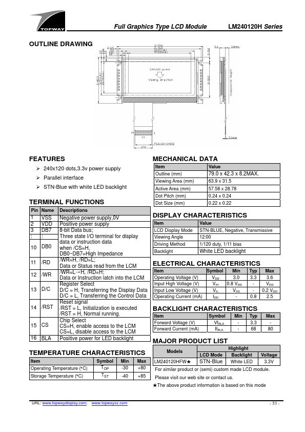
OUTLINE DRAWING Full Graphics Type LCD Module LM240120H Series FEATURES 240x120 dots,3.3v power supply Parallel interface STN-Blue with white LED backlight TERMINAL...
View more extracted text
pply Parallel interface STN-Blue with white LED backlight TERMINAL FUNCTIONS Pin Name Descriptions 1 VSS 2 VDD 3 DB7 :: 10 DB0 11 /RD 12 /WR 13 D/C 14 /RST 15 CS 16 BLA Negative power supply,0V Positive power supply 8-bit Data bus; Three state I/O terminal for display data or instruction data when /CS=H, DB0~DB7=High Impedance /WR=H, /RD=L; Data or Status read from the LCM /WR=L→H, /RD=H; Data or Instruction latch into the LCM Register Select D/C = H, Transferring the Display Data D/C = L, Transferring the Control Data Reset signal /RST = L, Initialization is executed /RST = H, Normal running.