OPB122A Overview
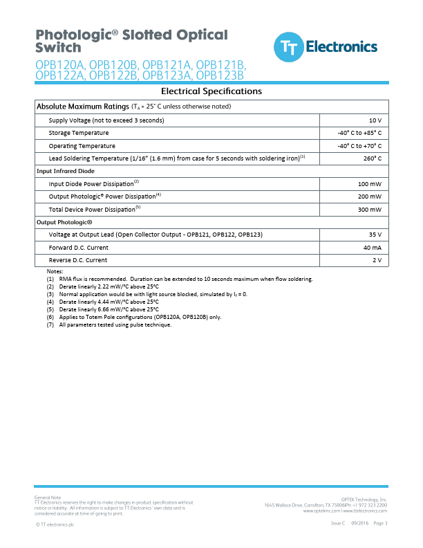
(1) RMA flux is remended. Duration can be extended to 10 seconds maximum when flow soldering. (2) Derate linearly 2.22 mW/°C above 25°C (3) Normal application would be with light source blocked, simulated by IF =.
| Part number | OPB122A |
|---|---|
| Datasheet | OPB122A OPB121A Datasheet (PDF) |
| File Size | 949.40 KB |
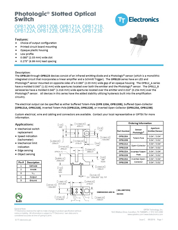
| Manufacturer | TT Electronics |
| Description | OPTICAL SWITCHES |
|
|
(1) RMA flux is remended. Duration can be extended to 10 seconds maximum when flow soldering. (2) Derate linearly 2.22 mW/°C above 25°C (3) Normal application would be with light source blocked, simulated by IF =.