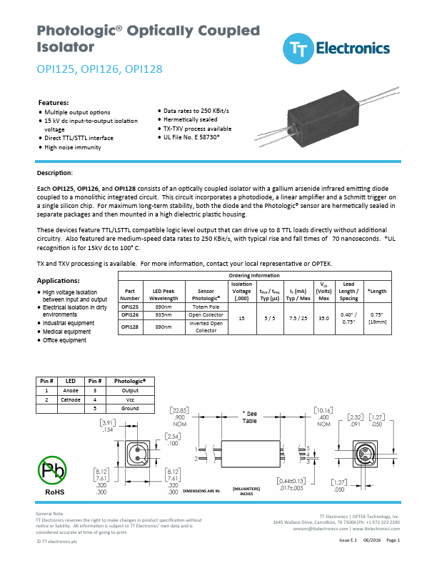
OPI125, OPI126, OPI128
OPI125 - Totem Pole Output
OPI126 - Open Collector Output
OPI127 - Inverted Totem Pole Output
OPI128 - Inverted Open Collector Output
Absolute Maximum Ratings (TA = 25o C unless otherwise noted)
Storage Temperature
Operating Temperature
Supply Voltage, VCC (not to exceed 3 seconds)
Input-to-Output Isolation Voltage(1)(2)
Lead Soldering Temperature (1/16” (1.6 mm) from case for 5 seconds with soldering iron)(3)
Input Diode
Forward DC Current
Reverse DC Voltage
Power Dissipation(4)
Output Photosensor
Output Photologic® Power Dissipation(5)
Duration of Output Short to VCC or Ground (OPI125, OPI127)
Duration of Output Short to VCC (OPI126, OPI128)
Voltage at Output Lead (OPI126, OPI128)
Notes:
(1) Measured with input and output leads shorted.
(2) UL recognition is for 15kV dc for one minute
(3) RMA flux is recommended. Duration can be extended to 10 seconds maximum when flow soldering.
(4) Derate linearly 1.33 mW/° C above 25° C.
(5) Derate linearly 3.40 mW/° C above 90° C.
-55° C to +100° C
-55° C to +100° C
+10 V
± 15 kVDC
260° C
25 mA
2V
200 mW
120 mW
1.00 second
1.00 second
35 V
General Note
TT Electronics reserves the right to make changes in product specification without
notice or liability. All information is subject to TT Electronics’ own data and is
considered accurate at time of going to print.
© TT electronics plc
TT Electronics | OPTEK Technology, Inc.
1645 Wallace Drive, Carrollton, TX 75006|Ph: +1 972 323 2200
sensors@ttelectronics.com | www.ttelectronics.com
Issue E.1 06/2016 Page 2