XC25BS7 Key Features
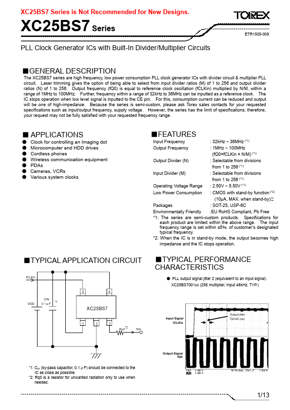
- 1: The series are semi-custom products. Specifications for each product are limited within the above range. The input fr
- 2: When the IC is in stand-by mode, the output bees high
| Part Number | Description |
|---|---|
| XC25BS3 | CMOS Low Power Consumption |
| XC25BS5 | PLL Clock Generator ICs with Built-In Divider/Multiplier Circuits (For Low Frequency range) |
| XC25BS5001ML | PLL Clock Generator ICs with Built-In Divider/Multiplier Circuits (For Low Frequency range) |
| XC25BS5001MR | PLL Clock Generator ICs with Built-In Divider/Multiplier Circuits (For Low Frequency range) |
| XC25BS6 | Divider Signal Output Clock Generator ICs |