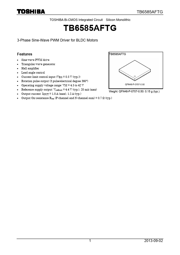
Datasheet4U Logo Datasheet4U.com

TB6585AFTG Datasheet 3-phase Sine-wave Pwm Driver

Manufacturer: Toshiba

Overview: TOSHIBA Bi-CMOS Integrated Circuit Silicon Monolithic TB6585AFTG TB6585AFTG 3-Phase Sine-Wave PWM Driver for BLDC.

General Description

Pin No 7 8 9 10 11 12 13 15 22 24 25 26 27 28 29 Pin name VM FG HWM HWP S-GND OSC/C OSC/R VSP TR CW/CCW RESET HVM HVP HUM HUP 30 Vrefout 31 32 33 34 35 36 37 39 46 48 1 2 3 4 5 6 14, 16, 17, 18, 19, 20, 21, 23, 38, 40, 41, 42, 43, 44, 45, 47 ML LL UL LA IV LPF PH Gout GinGin+ RS P-GND IR W V U N.C TB6585AFTG Description Motor power supply pin (VM = 4.5 to 42 V) Rotation speed output pin (3 pulses per electrical degree) W-phase Hall-signal input (−) W-phase Hall signal input (+) Signal ground Connection pin for a capacitor to control PWM oscillation Connection pin for a resistor to control PWM oscillation Speed control input Time setting pin for the anti-lock system Rotation direction select input Reset pin for disabling the outputs V-phase Hall-signal input (−) V-phase Hall-signal input (+) U-phase Hall-signal input (−) U-phase Hall-signal input (+) Reference voltage output (Vrefout = 4.4 V (typ.), Irefout = 20 mA (max)), connection pin

Key Features

  • TB6585AFTG.
  • Sine-wave PWM drive.
  • Triangular-wave generator.
  • Hall amplifier.
  • Lead angle control.
  • Current limit control input (VRS = 0.5 V (typ. )).
  • Rotation pulse output (3 pulse/electrical degree 360°).
  • Operating supply voltage range: VM = 4.5 to 42 V.
  • Reference supply output: Vrefout = 4.4 V (typ. ), 20 mA (max).
  • Output current: IOUT = 1.8 A (max), 1.2 A (typ. ) Weight: QFN48-P-0707-0.50: 0.15 g (typ. ).

TB6585AFTG Distributor