TL1WK-NW1L
TL1WK-NW1L is LED Lamps InGaN/Phosphor manufactured by Toshiba.
- Part of the TL1WK-NW1 comparator family.
- Part of the TL1WK-NW1 comparator family.
Features
(1) Size: 0.65 (L) mm × 0.65 (W) mm × 0.36 (H) mm (2) High luminous flux LED: 21.8 lm (typ.) @IF = 60 m A (3) Color: White (color temperature: 5000 K (typ.)) (4) Operating temperature range: Topr = -40 to 120 (5) Reflow-soldering is available.
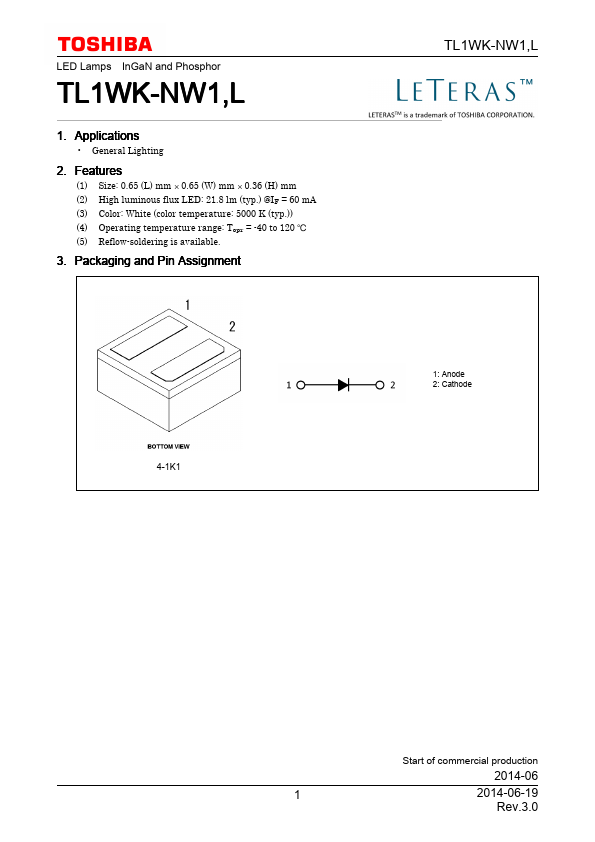
3. Packaging and Pin Assignment
4-1K1
TL1WK-NW1,L
1: Anode 2: Cathode
Start of mercial production
2014-06
1 2014-06-19 Rev.3.0
TL1WK-NW1,L
4. Absolute Maximum Ratings (Note) (Unless otherwise specified, Ta = 25 )
Characteristics
Symbol
Rating
Unit
Forward current (DC)
See Fig. 4.1.
180 m A
Power dissipation
PD 0.61 W
Operating temperature
Topr -40 to 120
Storage temperature
Tstg -40 to 120
Junction temperature A
(Note1)
Tj
Junction temperature B
(Note1)
Tj
Note:
Using continuously under heavy loads (e.g. the application of high temperature/current/voltage and the significant change in temperature, etc.) may cause this product to decrease in the reliability significantly even if the operating conditions (i.e. operating temperature/current/voltage, etc.) are within the absolute maximum ratings. Please design the appropriate reliability upon reviewing the Toshiba Semiconductor Reliability Handbook ("Handling Precautions"/"Derating Concept and Methods") and individual reliability data (i.e. reliability test report and estimated failure rate, etc).
Fig. 4.1 IF
- Ta (Note 1), (Note 2) Note 1: The junction-to-ambient thermal resistance, Rth(j-a), should be kept below 70 /W so that this product is not exposed to a condition beyond the absolute maximum ratings. Junction temperature A: For general lighting applications, the current rating should be limited within the range shown by the dotted line (A) (Tj ≤ 125 ) and derated for temperature. Heat dissipation performance should also be considered when selecting a printed circuit board. Junction temperature B: The device temperature is between lines A and B shown in Figure 4.1 (125 < Tj ≤ 150 ). Because the device bees so hot, it...