UMUR2040C
UMUR2040C is SWITCHMODE POWER RECTIFIERS manufactured by Unisonic Technologies.
DESCRIPTION
The UTC UMUR2040C is a switchmode power rectifier, it uses UTC’s advanced technology to provide customers with high voltage capability, low forward drop and low leakage current, etc.
The UTC UMUR2040C is suitable for use in switching power supplies, inverters and as free wheeling diodes.
- FEATURES
- Ultrafast and nanosecond recovery time
- High voltage capability
- Low forward drop
- Low leakage current
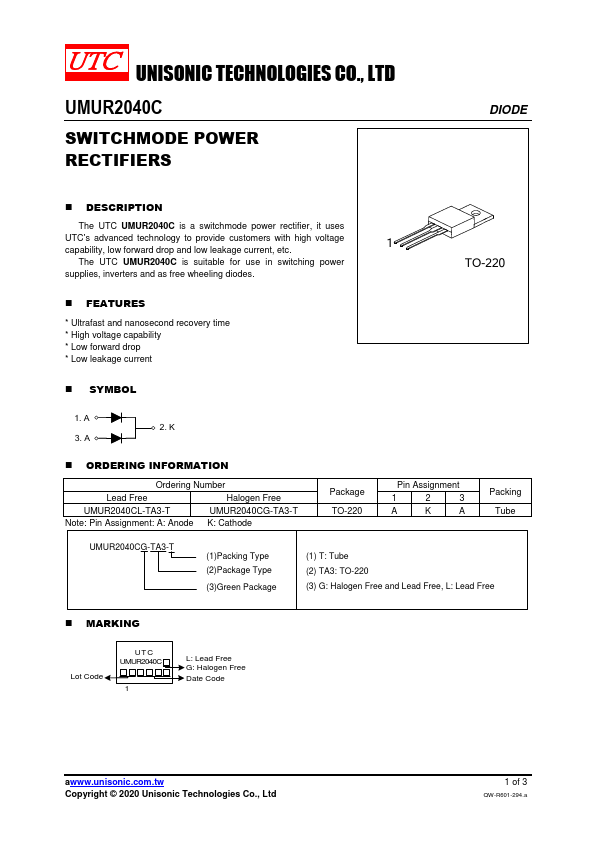
TO-220
- SYMBOL
1. A 2. K
3. A
- ORDERING INFORMATION
Ordering Number
Lead Free
Halogen Free
UMUR2040CL-TA3-T
UMUR2040CG-TA3-T
Note: Pin Assignment: A: Anode K: Cathode
Package TO-220
Pin Assignment 123 AKA
Packing Tube
UMUR2040CG-TA3-T
(1)Packing Type (2)Package Type (3)Green Package
(1) T: Tube (2) TA3: TO-220 (3) G: Halogen Free and Lead Free, L: Lead Free
- MARKING
Lot Code
UTC UMUR2040C
L: Lead Free G: Halogen Free
Date Code a.unisonic..tw Copyright © 2020 Unisonic Technologies Co., Ltd
1 of 3
QW-R601-294.a
DIODE
- ABSOLUTE MAXIMUM RATINGS
PARAMETER
SYMBOL
RATINGS
UNIT...