Vishay 80PFR40
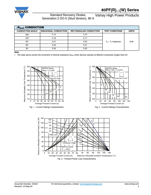
The table above shows the increment of thermal resistance RthJC when devices operate at different conduction angles than DC Maximum Allowable Case Temperature (°C) Maximum Allowable Case Temperature (°C) 180 80PF(R) Series 170 RthJC = 0.3 K/W 160 Conduction Angle 150 140 180° 130 120° 90° 120 30° 60° 110 0 10 20 30 40 50 60 70 80 90 Average Forward Current (A) Fig.| Part No. | 80PFR40 |
|---|---|
| Datasheet | 80PFR40 Download |
| Manufacturer |  Vishay |
| Description | Standard Recovery Diode |
| Buy | Stock & Price |
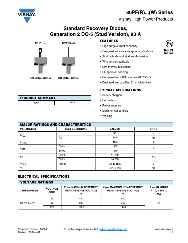
FEATURES
● High surge current capability● Designed for a wide range of applications
● Stud cathode and stud anode version
● Wire version available
● Low thermal resistance
● UL approval pending
● Compliant to RoHS directive 2002/95/EC
● Designed and qualified for multiple level PRODUCT SUMMARY IF(AV) 80 A
TYPICAL APPLICATIONS
● Battery chargers● Converters
● Power supplies
● Machine tool controls
● Welding MAJOR RATINGS AND CHARACTERISTICS PARAMETER TEST CONDITIONS IF(AV) IF(RMS) IFSM I2t VRRM TJ TC 50 Hz 60 Hz 50 Hz 60 Hz Range VALUES 80 140 126 1500 1570 11 250 10 230 400 to 1200 - 55 to 180
ELECTRICAL SPECIFICATIONS
VOLTAGE RATINGS TYPE NUMBER VOLTAGE CODE 40 80PF(R)...(W) 80 120 VRRM, MAXIMUM REPETITIVE PEAK REVERSE VOLTAGE V 400 800 1200 VRSM, MAXIMUM NON-REPETITIVE PEAK REVERSE VOLTAGE V 500 960 1440 UNITS A °C A A A2s V °C IRRM MAXIMUM AT TJ = 150 °C mA 9 Document Number: 93526 Revision: 20-May-09 For technical questions, contact: ind-modules@vishay.com 1 80PF(R)...(W) Series...