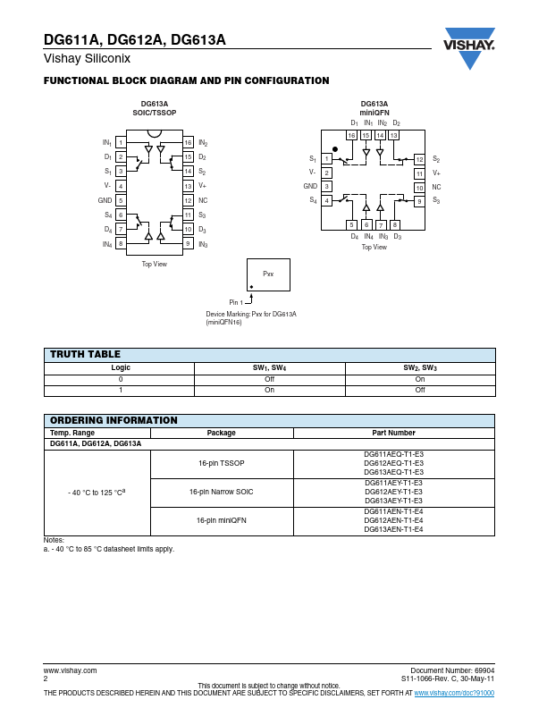
DG613A Overview
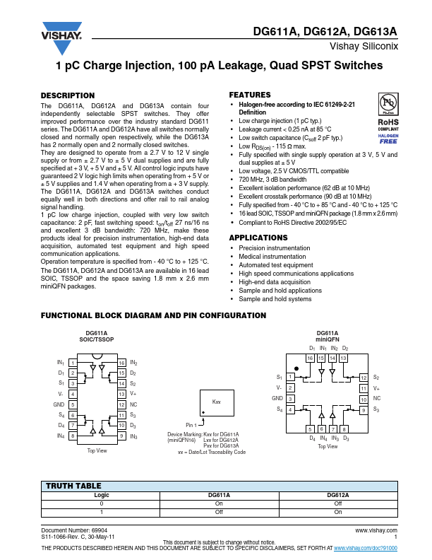
The DG611A, DG612A and DG613A contain four independently selectable SPST switches. They offer improved performance over the industry standard DG611 series. The DG611A and DG612A have all switches normally closed and normally open respectively, while the DG613A has 2 normally open and 2 normally closed switches.
DG613A Key Features
- Halogen-free according to IEC 61249-2-21 Definition
- Low charge injection (1 pC typ.)
- Leakage current < 0.25 nA at 85 °C
- Low switch capacitance (Csoff 2 pF typ.)
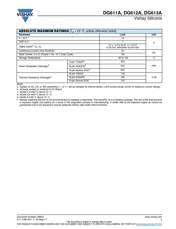
- Low RDS(on)
- 115 max
- Fully specified with single supply operation at 3 V, 5 V and
- Low voltage, 2.5 V CMOS/TTL patible
- 720 MHz, 3 dB bandwidth
- Excellent isolation performance (62 dB at 10 MHz)