S3K
S3K is Surface Mount Glass Passivated Rectifier manufactured by Vishay.
FEATURES
- Low profile package
Available
- Ideal for automated placement
- Glass passivated pellet chip junction
- Low forward voltage drop
- Low leakage current
- High forward surge capability
- Meets MSL level 1, per J-STD-020, LF maximum peak of 260 °C
- AEC-Q101 qualified available
- Automotive ordering code: base P/NHE3 or P/NHM3
- Material categorization: for definitions of pliance please see .vishay./doc?99912
TYPICAL APPLICATIONS
For use in general purpose rectification of power supplies, inverters, converters, and freewheeling diodes for consumer, automotive, and telemunication.
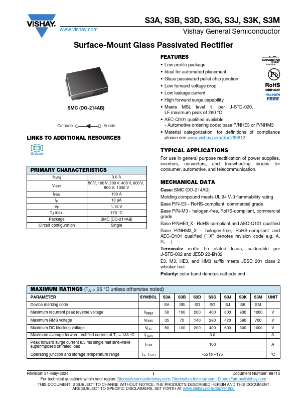
MECHANICAL DATA
Case: SMC (DO-214AB) Molding pound meets UL 94 V-0 flammability rating Base P/N-E3
- Ro HS-pliant, mercial grade Base P/N-M3
- halogen-free, Ro HS-pliant, mercial grade Base P/NHE3_X
- Ro HS-pliant and AEC-Q101 qualified Base P/NHM3_X
- halogen-free, Ro HS-pliant and AEC-Q101 qualified (“_X” denotes revision code e.g. A, B, ) Terminals: matte tin plated leads, solderable per J-STD-002 and JESD 22-B102 E3, M3, HE3, and HM3 suffix meets JESD 201 class 2 whisker test Polarity: color band denotes cathode end
MAXIMUM RATINGS (TA = 25 °C unless otherwise noted)
PARAMETER
SYMBOL S3A S3B S3D S3G S3J S3K S3M UNIT
Device marking code
SA SB SD SG SJ SK SM
Maximum recurrent peak reverse voltage
Maximum RMS voltage
Maximum DC blocking voltage Maximum average forward rectified current at TL = 133 °C Peak forward surge current 8.3 ms single half sine-wave superimposed on rated load
VRRM VRMS VDC IF(AV)
IFSM
50 100 200 400 600 800 1000 V
70 140 280 420 560 700
50 100 200 400 600 800 1000 V
Operating junction and storage temperature range
TJ, TSTG
-55 to...