Datasheet4U Logo Datasheet4U.com

VS-10ETS12-M3 Datasheet Input Rectifier Diode

Manufacturer: Vishay

Overview: www.vishay.com VS-10ETS...-M3 Series Vishay Semiconductors High Voltage, Input Rectifier Diode, 10 A 2 1 3 TO-220AC 2L Base cathode 2 1 3 Cathode Anode PRIMARY CHARACTERISTICS IF(AV) VR VF at IF IFSM TJ max. Package 10 A 800 V to 1200 V 1.

This datasheet includes multiple variants, all published together in a single manufacturer document.

General Description

High voltage rectifiers optimized for very low forward voltage drop with moderate leakage.

These devices are intended for use in main rectification (single or three phase bridge).

OUTPUT CURRENT IN TYPICAL APPLICATIONS APPLICATIONS SINGLE-PHASE BRIDGE Capacitive input filter TA = 55 °C, TJ = 125 °C common heatsink of 1 °C/W 12.0 THREE-PHASE BRIDGE 16.0 UNITS A MAJOR RATINGS AND CHARACTERISTICS SYMBOL CHARACTERISTICS IF(AV) VRRM IFSM VF TJ Sinusoidal waveform 10 A, TJ = 25 °C VALUES 10 800/1200 160 1.1 -40 to +150 VOLTAGE RATINGS PART NUMBER VS-10ETS08-M3 VS-10ETS12-M3 VRRM, MAXIMUM PEAK REVERSE VOLTAGE V 800 1200 VRSM, MAXIMUM NON-REPETITIVE PEAK REVERSE VOLTAGE V 900 1300 UNITS A V A V °C IRRM AT 150 °C mA 0.5 ABSOLUTE MAXIMUM RATINGS PARAMETER SYMBOL Maximum average forward current IF(AV) Maximum peak one cycle non-repetitive surge current IFSM Maximum I2t for fusing I2t Maximum I2√t for fusing I2√t TEST CONDITIONS TC = 105 °C, 180° conduction half sine wave 10 ms sine pulse, rated VRRM applied 10 ms sine pulse, no voltage reapplied 10 ms sine pulse, rated VRRM applied 10 ms sine pulse, no voltage reapplied t = 0.1 ms to 10 ms, no voltage reapplied VALUES 10 135 160 91 130 1300 UNITS A A2s A2√s Revision: 29-Nov

Key Features

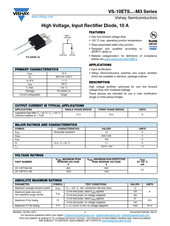
  • Very low forward voltage drop.
  • 150 °C max. operating junction temperature.
  • Glass passivated pellet chip junction.
  • Designed and qualified according to JEDEC®-JESD 47.
  • Material categorization: for definitions of compliance please see www. vishay. com/doc?99912.

VS-10ETS12-M3 Distributor