- Part: 3KP10
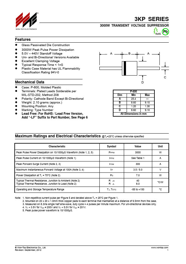
- Description: 3000W TRANSIENT VOLTAGE SUPPRESSOR
- Manufacturer: Won-Top Electronics
- Size: 96.42 KB
Overview
- Glass Passivated Die Construction
- 3000W Peak Pulse Power Dissipation
- 5.0V - 440V Standoff Voltage
- Uni- and Bi-Directional Versions Available
- Excellent Clamping Voltage
- Typical Response Time < 1nS
- Plastic Case Material has UL Flammability Classification Rating 94V-0 Mechanical Data
- Case: P-600, Molded Plastic
- Terminals: Plated Leads Solderable per
Datasheets by Manufacturer
- 3KP10 — GW — 3000 Watt Axial Lead TVS
- 3KP100A — HITANO — Transient Voltage Suppressors
- 3KP14A — Brightking — Transient Voltage Suppressors
- 3KP150CA — RFE — TRANSIENT VOLTAGE SUPPRESSOR
- 3KP14A — JGD — 3000Watts Transient Voltage Suppressors
- 3KP190CA — GW — 3000 Watt Axial Lead TVS
- 3KP190C — GW — 3000 Watt Axial Lead TVS
- 3KP17 — GW — 3000 Watt Axial Lead TVS
- 3KP11A — GW — 3000 Watt Axial Lead TVS
- 3KP150 — SOCAY — Axial Lead Transient Voltage Suppressors