Datasheet4U.com
🌙
SN74AHC1G00 Datasheet | Texas Instruments
Part:
SN74AHC1G00
Description:
Positive-NAND Gate
Manufacturer:
Texas Instruments
Size:
1.18 MB
Download SN74AHC1G00 Datasheet PDF
Related SN74AHC1G00 Datasheets
SN74AHC1G00-Q1 Positive-NAND Gate
SN74AHC1G02-EP Positive-NOR Gate
SN74AHC1G04 Single Inverter Gate
SN74AHC1G02 Positive-NOR Gate
SN74AHC1G04-Q1 Automotive Single Inverter Gate
Texas Instruments
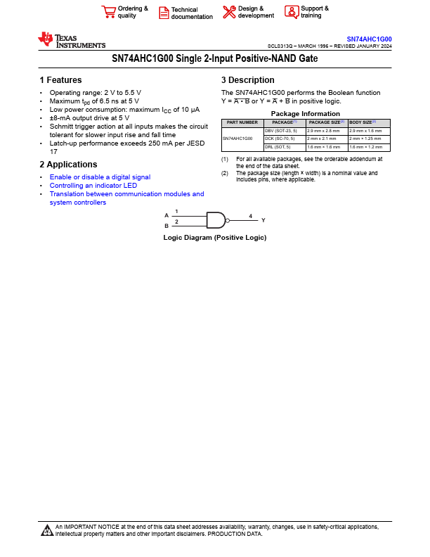
SN74AHC1G00
Description
.
Applications
Enable or disable a digital signal
×
Close