SN74AHCT16374
SN74AHCT16374 is 16-BIT EDGE-TRIGGERED D-TYPE FLIP-FLOPS manufactured by Texas Instruments.
SN54AHCT16374, SN74AHCT16374
16-BIT EDGE-TRIGGERED D-TYPE FLIP-FLOPS WITH 3-STATE OUTPUTS
SCLS337I
- MARCH 1996
- REVISED FEBRUARY 2000
D Members of the Texas Instruments
Widebus ™ Family
D EPIC ™ (Enhanced-Performance Implanted
CMOS) Process
D Inputs Are TTL-Voltage patible D Distributed VCC and GND Pins Minimize
High-Speed Switching Noise
D Flow-Through Architecture Optimizes PCB
Layout
D Latch-Up Performance Exceeds 250 m A Per
JESD 17
D ESD Protection Exceeds 2000 V Per
MIL-STD-883, Method 3015; Exceeds 200 V Using Machine Model (C = 200 p F, R = 0)
D Package Options Include Plastic Shrink
Small-Outline (DL), Thin Shrink Small-Outline (DGG), and Thin Very Small-Outline (DGV) Packages and 380-mil Fine-Pitch Ceramic Flat (WD) Package Using 25-mil Center-to-Center Spacings description
The ’AHCT16374 devices are 16-bit edge-triggered D-type flip-flops with 3-state outputs designed specifically for driving highly capacitive or relatively low-impedance loads. They are particularly suitable for implementing buffer registers, I/O ports, bidirectional bus drivers, and working registers.
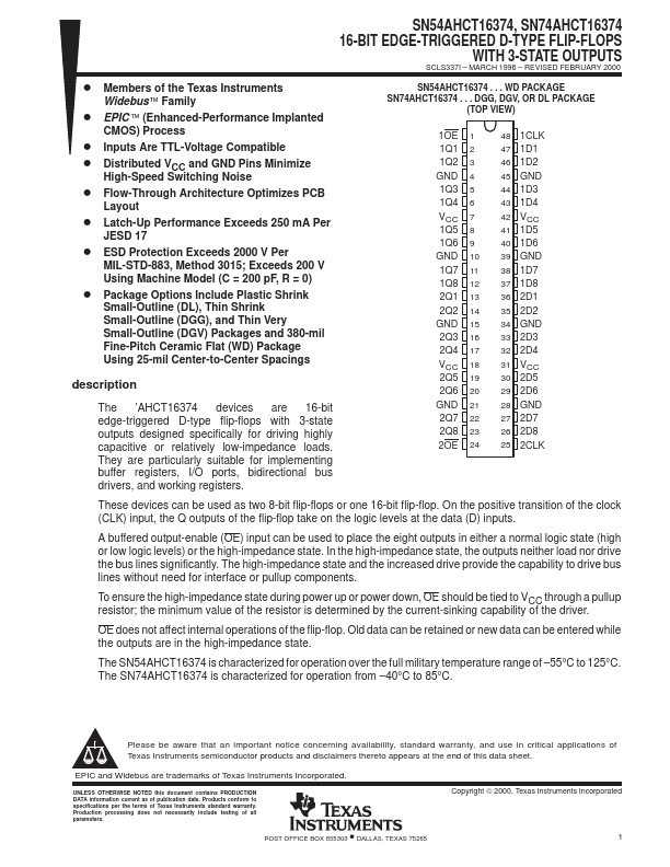
SN54AHCT16374 . . . WD PACKAGE SN74AHCT16374 . . . DGG, DGV, OR DL PACKAGE
(TOP VIEW)
1OE 1 1Q1 2 1Q2 3 GND 4 1Q3 5 1Q4 6 VCC 7 1Q5 8 1Q6 9 GND 10 1Q7 11 1Q8 12 2Q1 13 2Q2 14 GND 15 2Q3 16 2Q4 17 VCC 18 2Q5 19 2Q6 20 GND 21 2Q7 22 2Q8 23 2OE 24
48 1CLK 47 1D1 46 1D2 45 GND 44 1D3 43 1D4 42 VCC 41 1D5 40 1D6 39 GND 38 1D7 37 1D8 36 2D1 35 2D2 34 GND 33 2D3 32 2D4 31 VCC 30 2D5 29 2D6 28 GND 27 2D7 26 2D8 25 2CLK
These devices can be used as two 8-bit flip-flops or one 16-bit flip-flop. On the positive transition of the clock (CLK) input, the Q outputs of the flip-flop take on the logic levels at the data (D) inputs.
A buffered output-enable (OE) input can be used to place the eight outputs in either a normal logic state (high or low logic levels) or the high-impedance state. In the high-impedance state, the outputs neither load nor drive the bus lines significantly. The...