SN74HC112N Overview
Key Specifications
Package: PDIP
Mount Type: Through Hole
Pins: 16
Operating Voltage: 5 V
Description
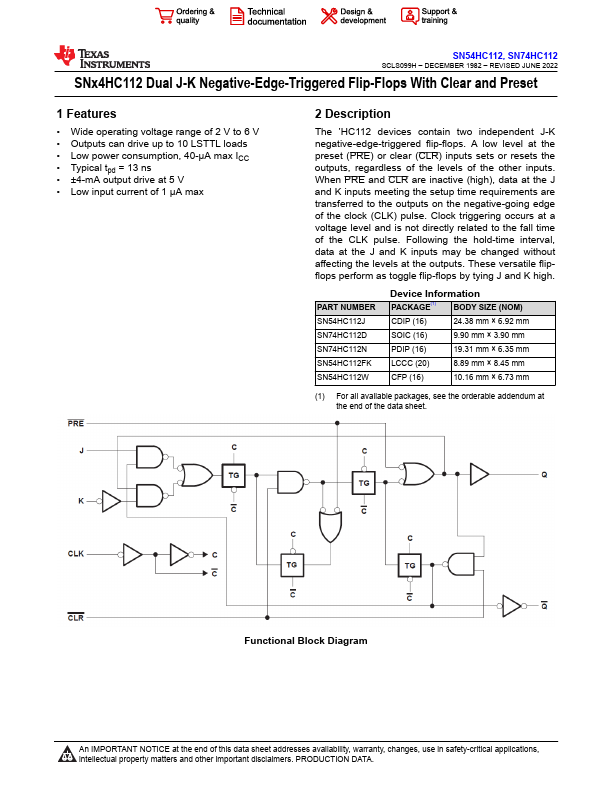
The ’HC112 devices contain two independent J-K negative-edge-triggered flip-flops. A low level at the preset (PRE) or clear (CLR) inputs sets or resets the outputs, regardless of the levels of the other inputs.
Key Features
- Wide operating voltage range of 2 V to 6 V
- Outputs can drive up to 10 LSTTL loads
- Low power consumption, 40-μA max ICC
- Typical tpd = 13 ns
- ±4-mA output drive at 5 V