Datasheet Summary
74HC2G66; 74HCT2G66
Dual single-pole single-throw analog switch
Rev. 11
- 6 November 2018
Product data sheet
1. General description
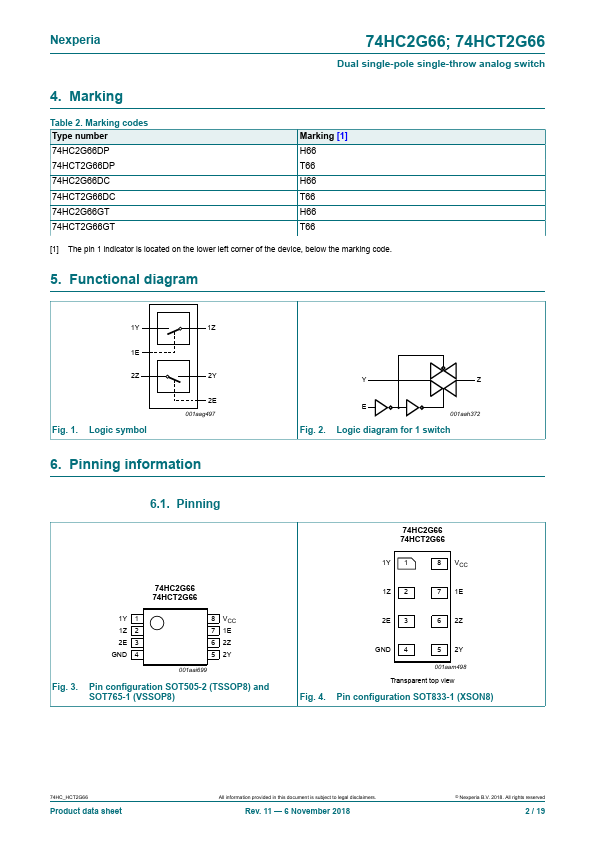
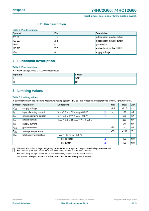
The 74HC2G66; 74HCT2G66 is a dual single pole, single-throw analog switch. Each switch has two input/output terminals (nY and nZ) and a digital enable input (nE). When nE is LOW, the analog switch is turned off. Inputs include clamp diodes. This enables the use of current limiting resistors to interface inputs to voltages in excess of VCC.
2. Features and benefits
- Wide supply voltage range from 2.0 V to 10.0 V for 74HC2G66
- Very low ON resistance:
- 41 Ω (typ.) at VCC = 4.5 V
- 30 Ω (typ.) at VCC = 6.0 V
- 21 Ω (typ.) at VCC = 9.0 V
- High noise...