onsemi FGH80N60FD2
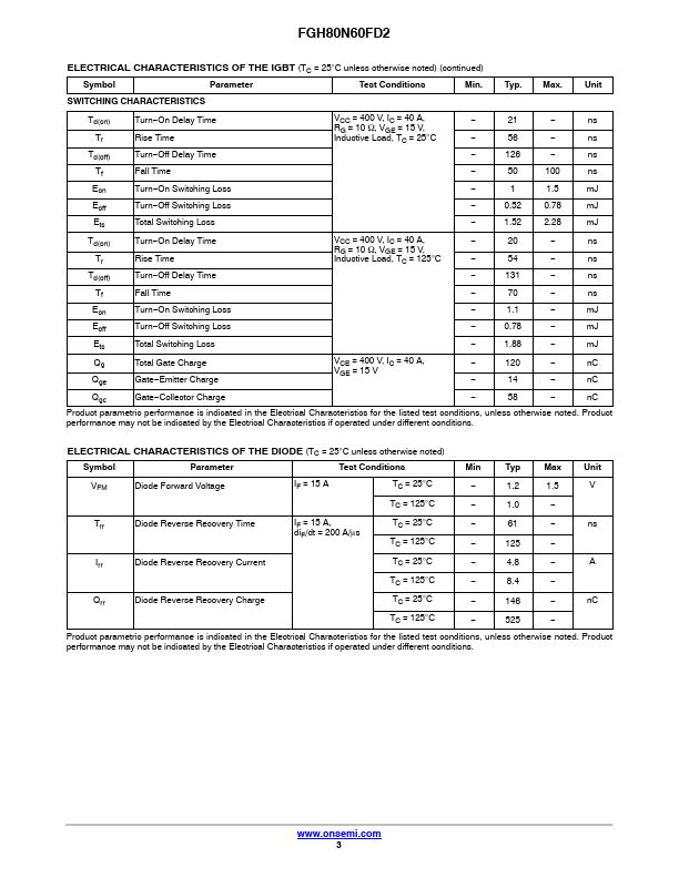
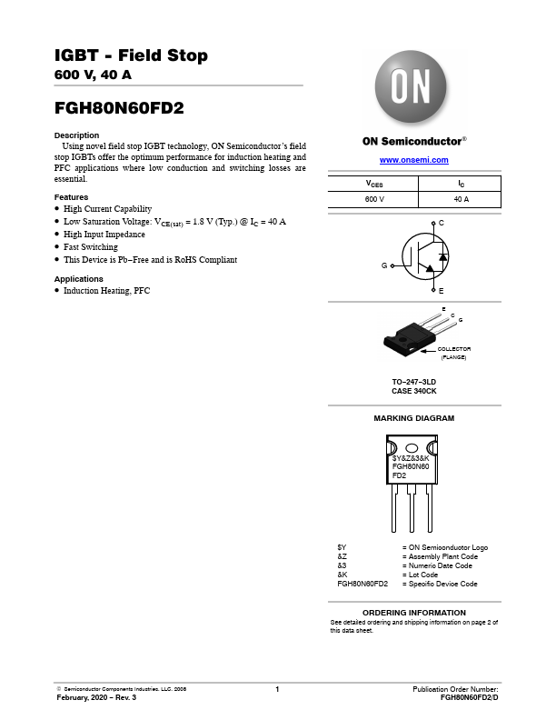
This Device is Pb−Free and is RoHS Compliant Applications • Induction Heating, PFC VCES 600 V IC 40 A C G E E C G COLLECTOR (FLANGE) TO−247−3LD CASE 340CK MARKING DIAGRAM $Y&Z&3&K FGH80N60 FD2 © Semiconductor Components Industries, LLC, 2008 February, 2020 − Rev. for Soldering Purposes, 1/8” from Case for 5 Seconds 300 °C Stresses exceeding those listed in the Maximum Ratings table may damage the device.| Part No. | FGH80N60FD2 |
|---|---|
| Datasheet | FGH80N60FD2 Download |
| Manufacturer |  onsemi |
| Description | IGBT |
| Buy | Stock & Price |
DESCRIPTION
Using novel field stop IGBT technology, ON Semiconductor’s field stop IGBTs offer the optimum performance for induction heating and PFC applications where low conduction and switching losses are essential.FEATURES
● High Current Capability● Low Saturation Voltage: VCE(sat) = 1.8 V (Typ.) @ IC = 40 A
● High Input Impedance
● Fast Switching
● 3 $Y &Z &3 &K FGH80N60FD2 = ON Semiconductor Logo = Assembly Plant Code = Numeric Date Code = Lot Code = Specific Device Code ORDERING INFORMATION See detailed ordering and shipping information on page 2 of this data sheet. 1 Publication Order Number: FGH80N60FD2/D FGH80N60FD2
ABSOLUTE MAXIMUM RATINGS
SymbolDESCRIPTION
Ratings Unit VCES Collector to Emitter Voltage 600 V VGES Gate−Emitter Voltage ±20 V IC Collector Current TC = 25°C 80 A TC = 100°C 40 A ICM (Note 1) Pulsed Collector Current TC = 25°C 160 A PD Maximum Power Dissipation TC = 25°C 290 W TC = 100°C 116 W TJ Operating Junction Temperature −55 to +150 °C TSTG Storage Temperature Range −55 to +150 °C TL Maximum Lead Temp.